Process for the production of plates made of transparent plastic material with non-transparent areas

a technology of transparent plastic and non-transparent areas, applied in the direction of molds, household objects, applications, etc., can solve the problems of affecting the optical and mechanical properties of the plate, unable to achieve sufficiently high quality, and unable to eliminate some typical aesthetic and optical defects, etc., to achieve optimal optical and mechanical properties, and low stress

a technology of transparent plastic and non-transparent areas, applied in the direction of molds, household objects, applications, etc., can solve the problems of affecting the optical and mechanical properties of the plate, unable to achieve sufficiently high quality, and unable to eliminate some typical aesthetic and optical defects, etc., to achieve optimal optical and mechanical properties, and low stress

US20060076711A1Active Publication Date: 2006-04-13INGLASS SRL

Image

  • Process for the production of plates made of transparent plastic material with non-transparent areas
  • Process for the production of plates made of transparent plastic material with non-transparent areas
  • Process for the production of plates made of transparent plastic material with non-transparent areas

Examples


Embodiment Construction

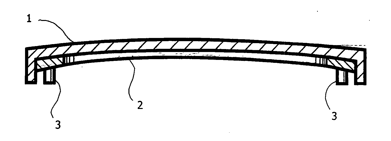
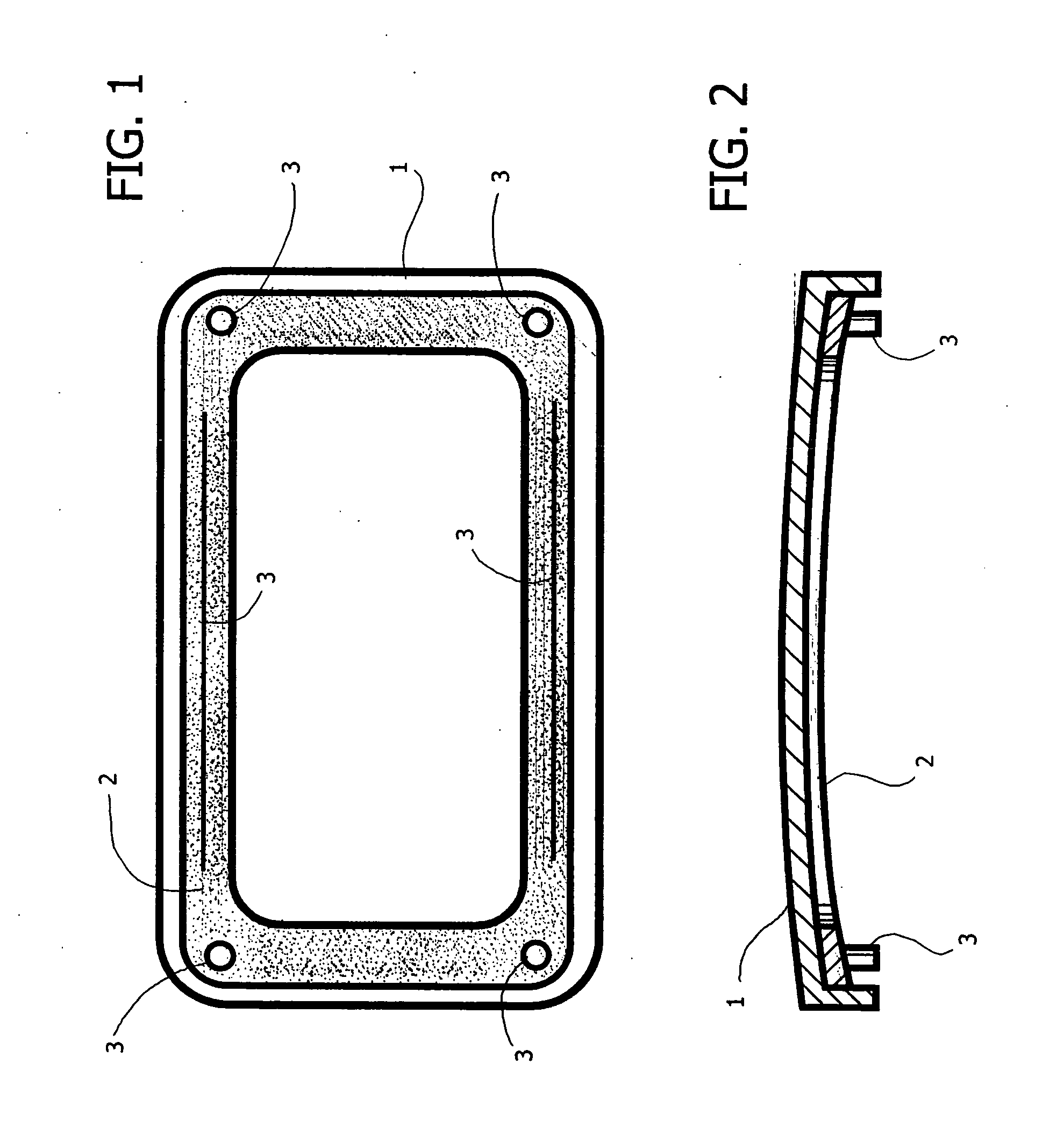
[0029]FIGS. 1 and 2 of the annexed plate of drawings are schematic representations of an example of a product made of bi-component plastic material obtained with the process according to the invention.

[0030] The product is constituted by a plate 1 made of transparent plastic material, typically polycarbonate, on the dorsal face of which is applied a perimetral frame 2 made of non-transparent plastic material, formed with appendages and projections 3 usable for the assembly of the plate in the condition of use.

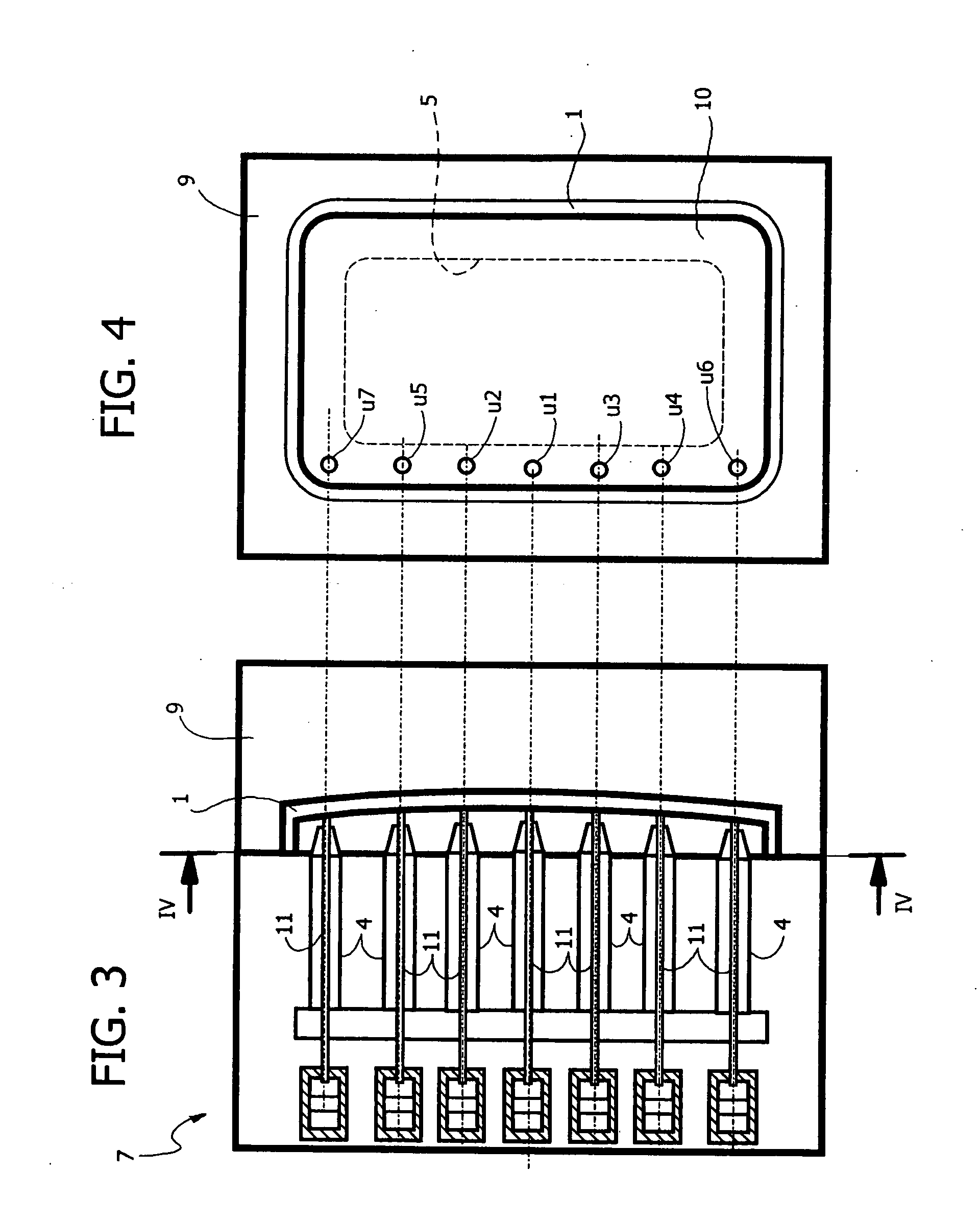
[0031] The process for the production of such a bi-component product envisages two successive steps, described in what follows with reference to FIGS. 3, 4 and 5, 6, respectively.

[0032] It should be noted that the process according to the invention can be implemented on a press of the stack-mould type with rotating central surface.

[0033] In this case, two moulding stations will be provided, the first designated by 7 and the second by 8, in a position corresponding to which ...


PUM

PropertyMeasurementUnit
Areaaaaaaaaaaa
Transparencyaaaaaaaaaa
Injection velocityaaaaaaaaaa

Abstract

Described herein is a process for the production of plates made of plastic material by means of sequential injection with the mould half-open and a subsequent step of compression obtained by closing the mould.

Description

CROSS-REFERENCE TO RELATED APPLICATIONS [0001] This application claims priority from Italian application number TO2004A000700, filed on Oct. 11, 2004, the entire disclosure of which is incorporated herein by reference. [0002] This application also relates to U.S. patent application Ser. No. (to be assigned) (Attorney Docket No. 2177.007), filed on the same day as the present patent application, and titled β€œAN APPARATUS AND A METHOD FOR THE INJECTION-COMPRESSION MOULDING OF ARTICLES MADE OF PLASTIC MATERIAL WITH TWO COMPONENTS,” the contents of which are incorporated herein by reference. [0003] This application also relates to U.S. patent application Ser. No. (to be assigned) (Attorney Docket No. 2177.009), filed on the same day as the present patent application, and titled β€œA PROCESS FOR THE PRODUCTION OF PLATES MADE OF TRANSPARENT PLASTIC MATERIAL WITH NON-TRANSPARENT OVERINJECTED PARTS,” the contents of which are incorporated herein by reference. [0004] This application also relat...

Claims


Application Information

Patent Timeline
13 Apr 2006
Publication
US20060076711A1
IPC
B29C45/16
CPC
B29C45/0025; B29C45/16; B29C45/561; B29C2045/0032; B29C2045/565; B29L2031/3055; B29L2031/345; B29L2031/7782
Inventors
ROSSANESE, AFRO; BAZZO, MAURIZIO