Eureka AIR delivers breakthrough ideas for toughest innovation challenges, trusted by R&D personnel around the world.

Subsea system and method for protecting equipment of a subsea system

a subsea system and equipment technology, applied in the field of subsea systems, can solve the problems of increasing project capital expenditures and dramatically, and achieve the effects of reducing the required pressure rating of subsea equipment, high level of safety of the subsea system, and reducing project capital expenditures

Active Publication Date: 2010-03-25
CHEVROU USA INC
View PDF9 Cites 25 Cited by
  • Summary
  • Abstract
  • Description
  • Claims
  • Application Information

AI Technical Summary

Benefits of technology

[0007]Provided is a subsea system that allows for reduced project capital expenditures by taking into account external hydrostatic pressure experienced by subsea equipment As a result, the required pressure rating of the subsea equipment is reduced. A high level of safety of the subsea system is maintained by including a protection system (i.e., a barrier) within the subsea system.

Problems solved by technology

Subsea systems are usually designed to work across high pressure differentials (e.g. full wellhead shut-in pressure versus operating flow pressure) even when normal operating flow pressure is only a small fraction of full wellhead shut-in pressure, which dramatically increases project capital expenditures.

Method used


Image

  • Subsea system and method for protecting equipment of a subsea system
  • Subsea system and method for protecting equipment of a subsea system
  • Subsea system and method for protecting equipment of a subsea system

Examples


Embodiment Construction

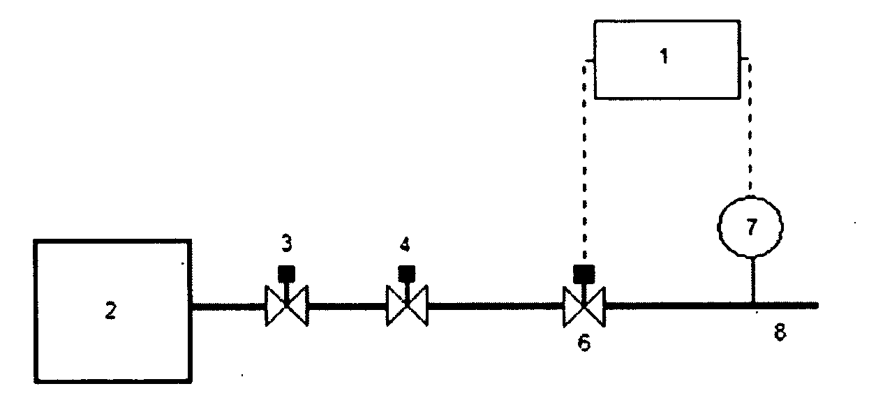
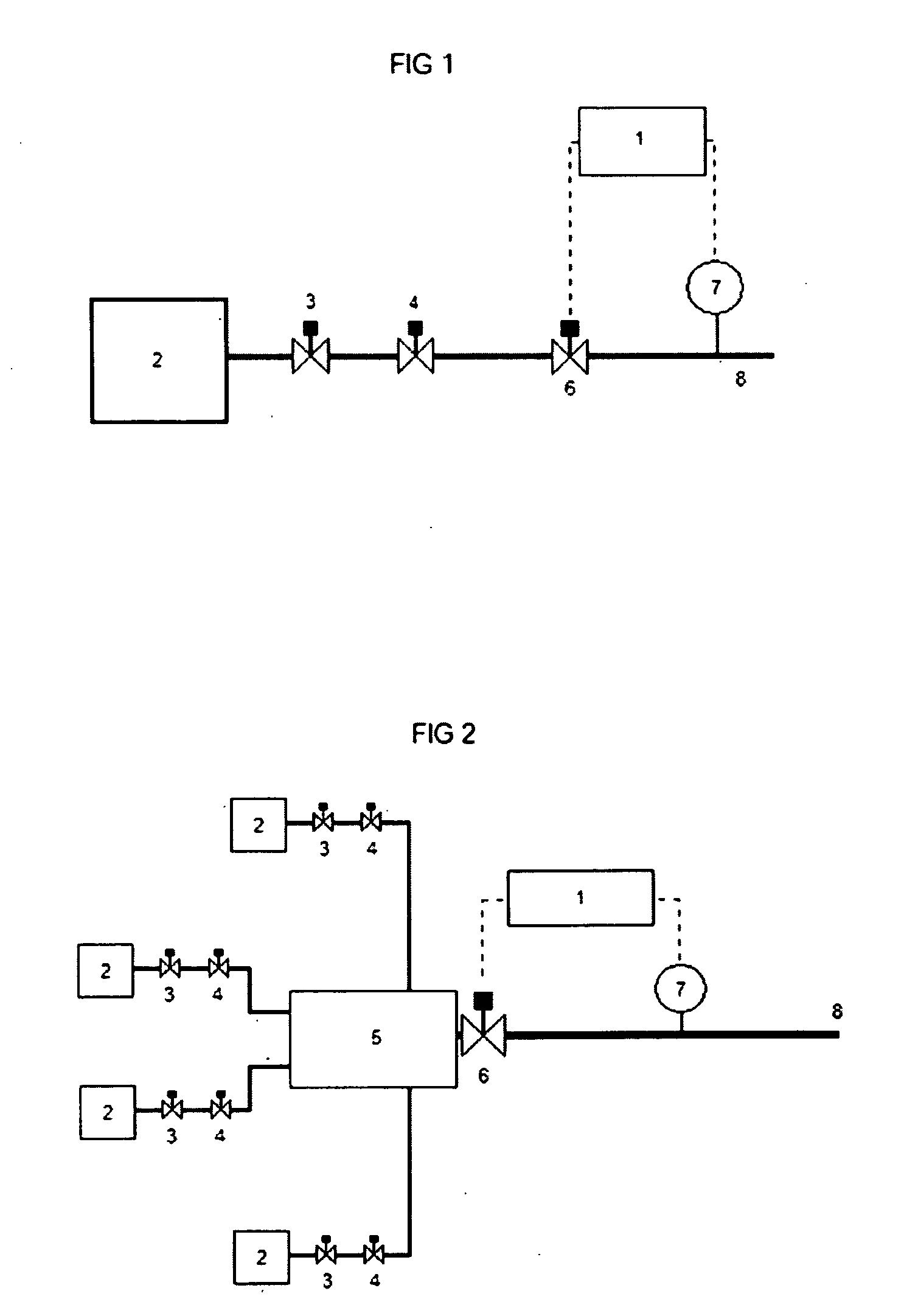
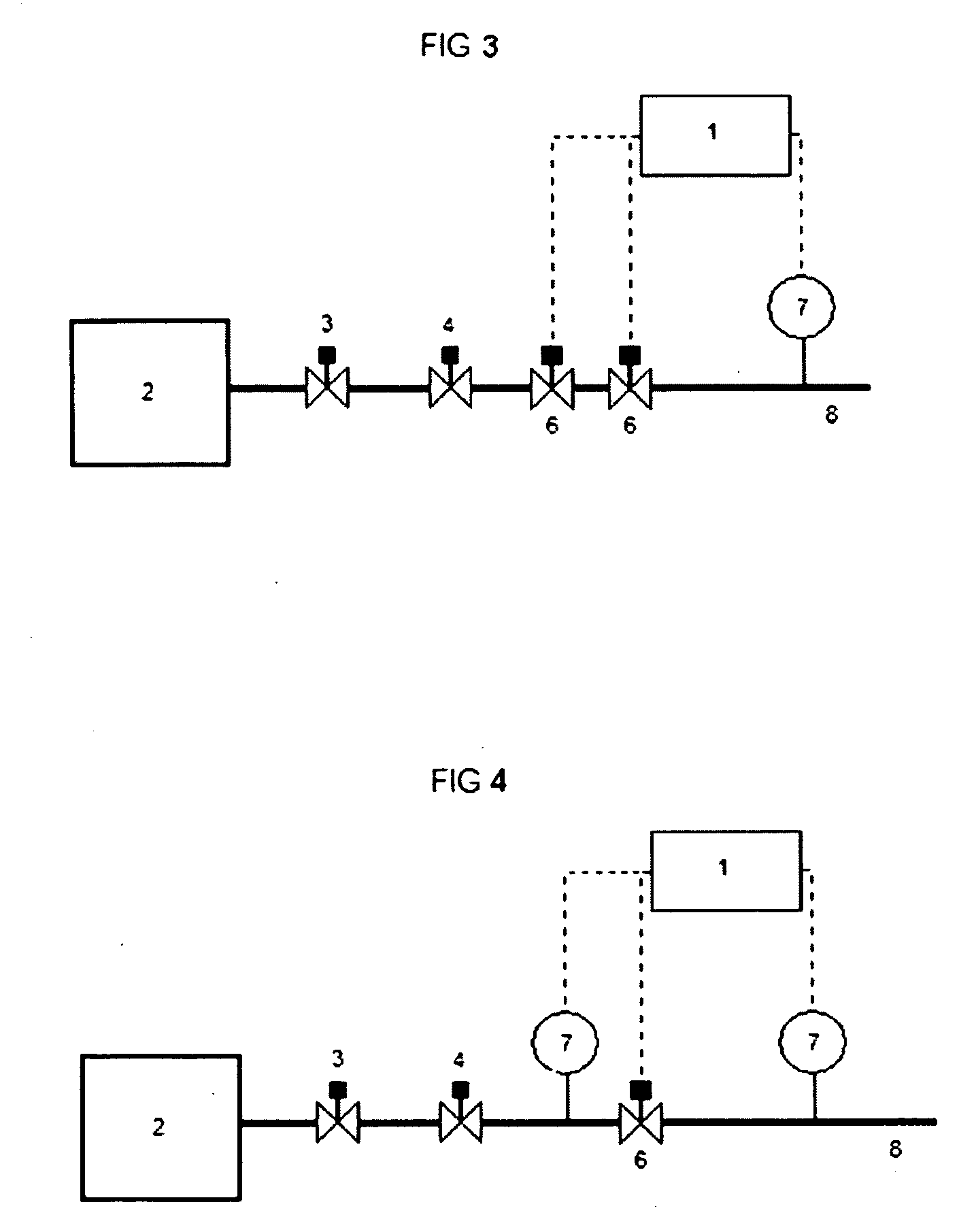
[0018]A high integrity protection system for subsea equipment is provided in the presently disclosed systems and methods. In some cases, the presently disclosed systems and methods can substantially reduce the costs of subsea equipment by reducing the pressure rating (e.g., the size) of subsea tree valves and / or subsea manifold valves. The presently disclosed systems and methods can also reduce installation / mobilization costs by reducing the weight of subsea equipment. Further, the presently disclosed systems and methods can protect subsea equipment (e.g. pipeline, tree, manifold, valve(s), etc.) from operating across high pressure differentials. The presently disclosed systems and methods can protect the subsea equipment from operating across high pressure differentials by shutting down a barrier (e.g. one or more high pressure rated valves) located downstream of the wellbore.

[0019]The presently disclosed subsea system takes into account external hydrostatic pressure experienced by...


PUM


Abstract

A subsea system comprises a wellbore within a reservoir, equipment downstream of the wellbore, and a barrier connected to the equipment. The equipment is rated for a maximum pressure that is less than a maximum reservoir pressure and equal to or greater than the maximum reservoir pressure less external hydrostatic pressure experienced by the equipment. The barrier is rated for a maximum pressure that is equal to or greater than the maximum reservoir pressure.

Description

BACKGROUND OF THE INVENTION[0001]1) Field of the invention[0002]The present invention relates to a subsea system and an associated method for protecting equipment of a subsea system, e.g., for use in a subsea system for transporting oil, gas, and or other fluids from a subsea well.[0003]2) Description of Related Art[0004]Subsea systems are usually designed to work across high pressure differentials (e.g. full wellhead shut-in pressure versus operating flow pressure) even when normal operating flow pressure is only a small fraction of full wellhead shut-in pressure, which dramatically increases project capital expenditures. Subsea systems can comprise protection systems to deal with occasional high pressure differentials, for example, by retaining high pressure within a section of the system capable of withstanding the pressure, which prevents the remainder of the system from being exposed to pressure which may exceed its pressure rating. Thus, the protection systems safeguard equipm...

Claims


Application Information

Patent Timeline
Patent Type & Authority Applications(United States)
IPC IPC(8): F16K17/02
CPCE21B43/01E21B41/0007Y10T137/7762Y10T137/0379
Inventor RATCLIFFE, ANTHONY JAMES
Owner CHEVROU USA INC
Why Eureka
Eureka Blog
Learn More