

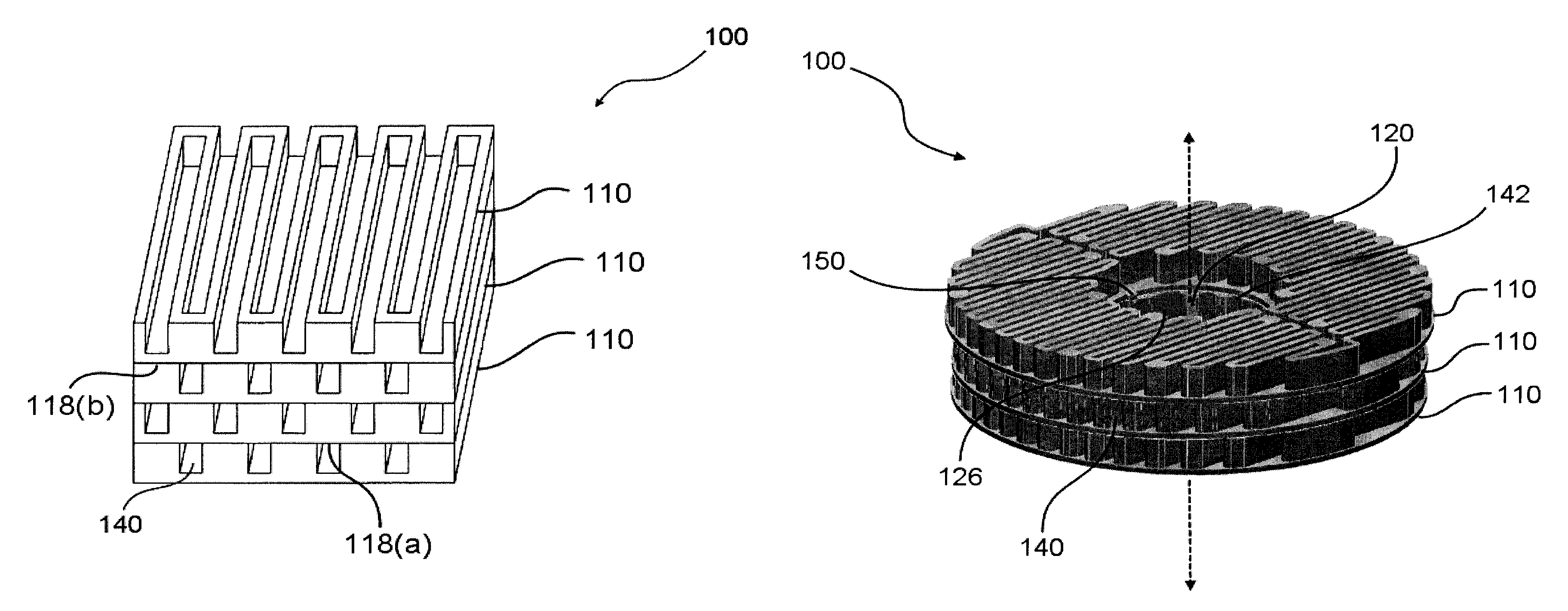
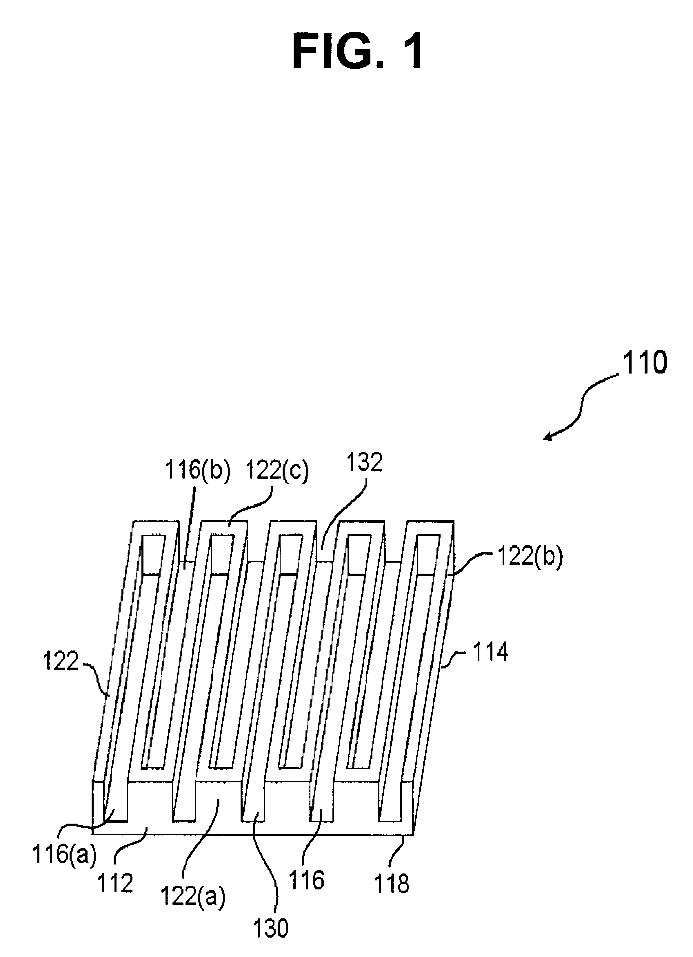
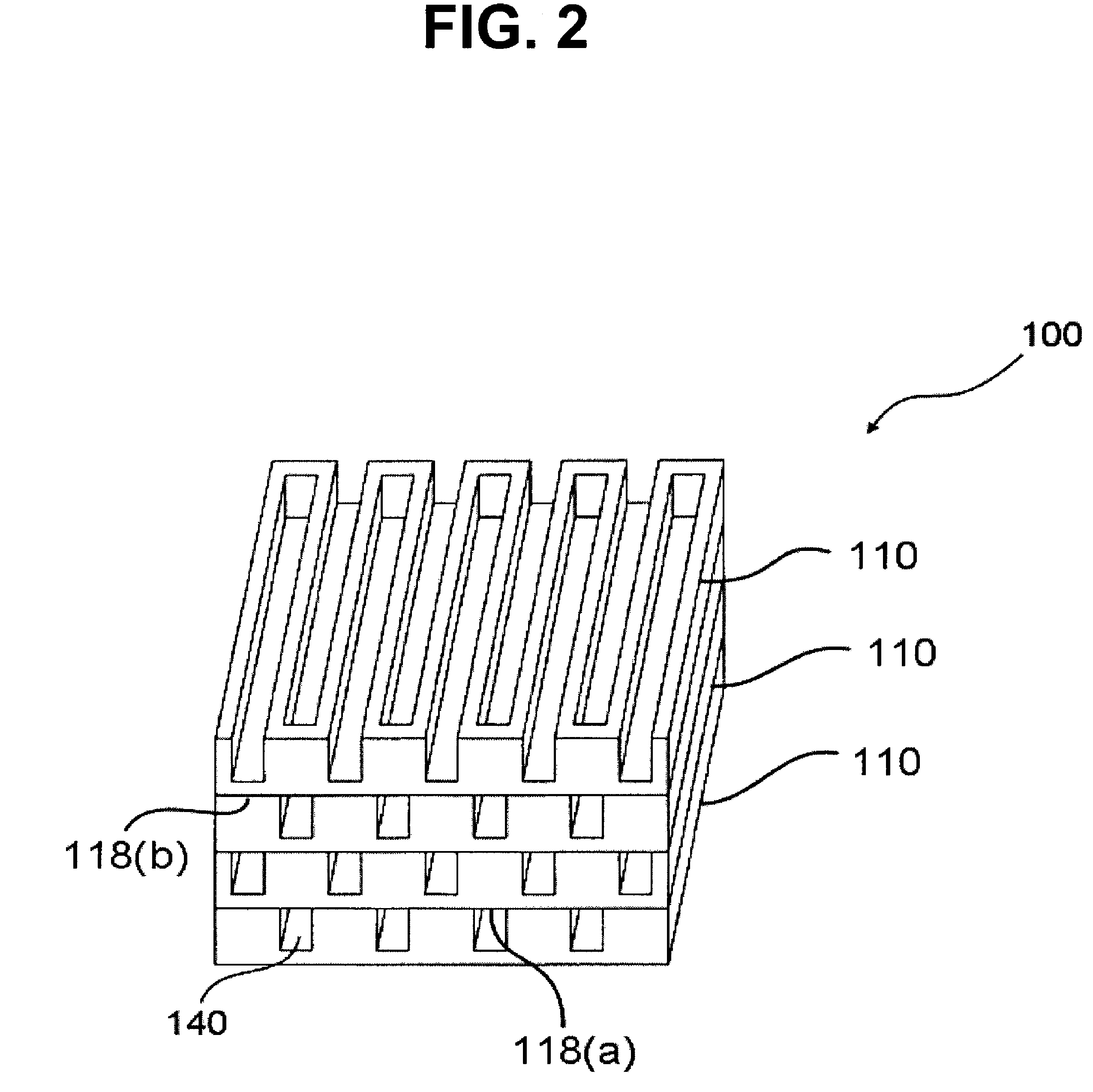
Modular filter assembly
a filter body and module technology, applied in the field of porous filters, can solve the problems of inability to achieve significant increases in surface area of conventional filter technology, inability to increase the size of a filter beyond the conventional dimension of the filter body, and limited filter capacity and effectiveness, so as to achieve convenient customization, increase the surface area, and increase the filtering capacity
- Summary
- Abstract
- Description
- Claims
- Application Information
AI Technical Summary
Benefits of technology
Problems solved by technology
Method used
Image

Examples
Embodiment Construction
[0022]The following description of the invention is provided as an enabling teaching of the invention in its best, currently known embodiment. To this end, those skilled in the relevant art will recognize and appreciate that many changes can be made to the various embodiments of the invention described herein, while still obtaining the beneficial results of the present invention. It will also be apparent that some of the desired benefits of the present invention can be obtained by selecting some of the features of the present invention without utilizing other features. Accordingly, those who work in the art will recognize that many modifications and adaptations to the present invention are possible and can even be desirable in certain circumstances and are a part of the present invention. Thus, the following description is provided as illustrative of the principles of the present invention and not in limitation thereof.
[0023]As used herein, the singular forms “a,”“an” and “the” incl...
PUM
| Property | Measurement | Unit |
|---|---|---|
| thickness | aaaaa | aaaaa |
| thickness | aaaaa | aaaaa |
| thickness | aaaaa | aaaaa |
Abstract
Description
Claims
Application Information