Rotating multi-monolith bed movement system for removing co2 from the atmosphere

a multi-monolith bed and movement system technology, applied in the direction of separation processes, dispersed particle separation, chemistry apparatus and processes, etc., can solve the problems of no feasible way to avoid using fossil fuels during the rest of the century, no solution, etc., to achieve lower overall costs, lower capital expenses, and high efficiency

Active Publication Date: 2015-10-01
GLOBAL THERMOSTAT OPERATIONS LLC
View PDF3 Cites 17 Cited by
  • Summary
  • Abstract
  • Description
  • Claims
  • Application Information

AI Technical Summary

Benefits of technology

[0009]The present invention provides further new and useful systems and methods for removing carbon dioxide from a mass of carbon dioxide laden air, at higher efficiencies and lower overall costs including lower capital expenses (“CAPEX”) and tower operating expenses (“OPEX”).
[0014]Generally, a longer time is required for adsorption of CO2 from ambient air than for the release of the CO2 in the regeneration step. With the current generation of sorbent this difference will require an adsorption period approximately ten times greater for the adsorption step compared with that required for CO2 release and sorbent regeneration, when treating ambient air. Thus a system with ten monoliths and a single regeneration unit has been adopted as the current basis for an individual rotating system. If the performance of the sorbent is improved over time, this ratio of adsorption time to desorption time, and thus the number of monoliths, required in a system, should be reduced. In particular, if a higher loading embodiment of the sorbent is used a one hour adsorption time would be viable, thus requiring one regeneration box to serve only five monoliths. In addition the relative treatment times will vary with the concentration of CO2 in the gas mixture treated, such that the higher the CO2 content, the shorter the adsorption time relative to the regeneration time, e.g., by mixing a combustion effluent (“flue gas”) with the ambient air through a gas mixer.
[0015]The chemical and physical activity within the monoliths, both during the adsorption cycle and the regeneration cycle in the sealed box, is substantially the same as is described in prior copending applications Ser. Nos. 13 / 886,207 and 13 / 925,679. The disclosures of those copending applications are incorporated by reference herein as if repeated in fill, as modified by the new disclosure presented herein. In the system according to the present invention, each rotating system provides one sealable regeneration box for each group of rotating monoliths, the number of monoliths being dependent upon the relative times to achieve the desired adsorption and the desired regeneration. In addition, it has been found that greater efficiencies and lower costs are achieved by spatially relating and temporally operating two of the rotating systems in a suitable relationship to allow the regeneration boxes for the two rotating monolith systems to interact, such that each is preheated by the remaining heat in the other as a result of regeneration in the other; this also efficiently cools down the regenerated monolith before it is returned to its adsorption cycle on the rotating track.
[0016]This interaction between the regeneration boxes is achieved in accordance with this invention, by lowering the pressure of the first box system so that the steam and water remaining in the first box evaporate after the release of CO2, and the system cools to the saturation temperature of the steam at its lowered partial pressure. Furthermore, as described below, the heat released in this process is used to pre-heat the second sorbent bed and thus provides approximately 50% sensible heat recovery, with a beneficial impact on energy and water use. This concept can be used even if an oxygen resistant sorbent is utilized. The sensitivity of the sorbent to oxygen de-activation at higher temperatures is being addressed during the development process and it is anticipate(that its performance will be improved over time.
[0017]As discussed above, the sorbent bed is preferably cooled before it is exposed to air so as to avoid de-activation by the oxygen in the air. This cooling is achieved by towering the system pressure and thus lowering the steam saturation temperature. This has been shown to be effective in eliminating the sorbent deactivation issue as it lowers the temperature of the system. There is thus a significant amount of energy removed from the bed that is cooled during the de-pressurization step. A fresh bed that has finished its CO2 adsorption step has to be heated to release the CO2 and regenerate the sorbent. This heat could be provided solely by the atmospheric pressure steam, but this is an additional operating cost. In order to minimize this operating cost, a two-bed design concept has been developed. In this concept the heat that is removed from the box that is being cooled by reducing the system pressure, and thus the steam saturation temperature, is used to partially pre-heat a second box containing a bed that has finished adsorbing CO2 from the air and which is to be heated to start the CO2 removal and sorbent regeneration step. Thus the steam usage is reduced by using heat from the cooling of the first box to increase the temperature of the second box. The remaining heat duty for the second box is achieved by adding steam, preferably at atmospheric pressure. This process is repeated for the other rotating monoliths in each of the two boxes and improves the thermal efficiency of the system.

Problems solved by technology

However, there is no feasible way to avoid using fossil fuels during the rest of this century if we are to have the energy needed for economic prosperity and avoid energy shortfalls that could lead to conflict.
It is also clear that there is no solution that only reduces the ongoing human contributions to carbon dioxide emissions that can successfully remove the risk of climate change.

Method used


Image

  • Rotating multi-monolith bed movement system for removing co2 from the atmosphere
  • Rotating multi-monolith bed movement system for removing co2 from the atmosphere
  • Rotating multi-monolith bed movement system for removing co2 from the atmosphere

Examples


Embodiment Construction

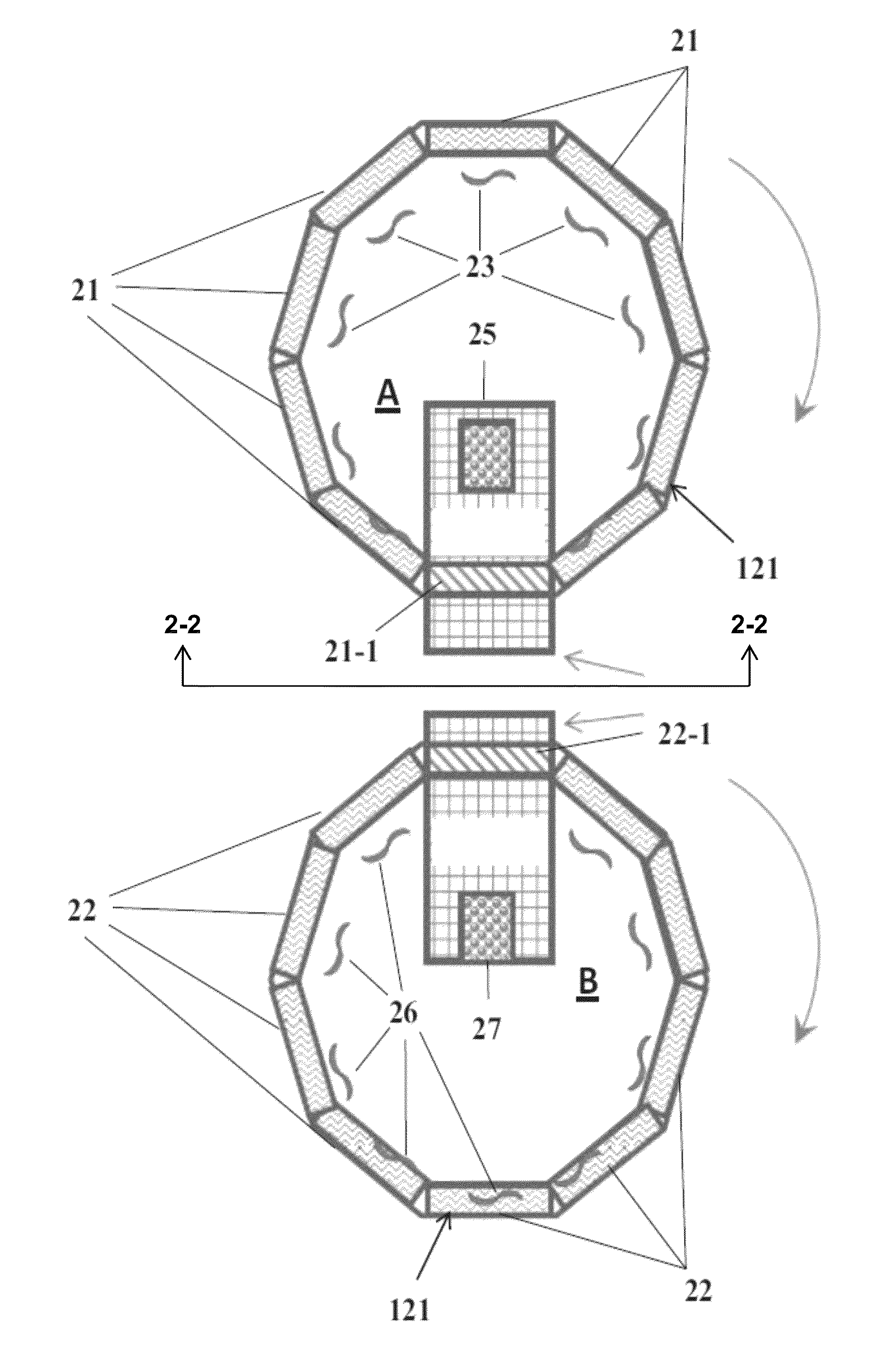
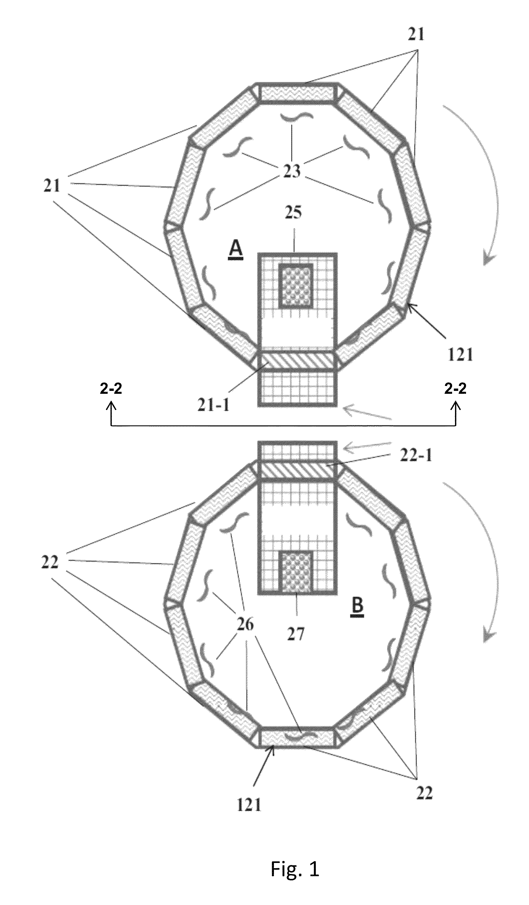
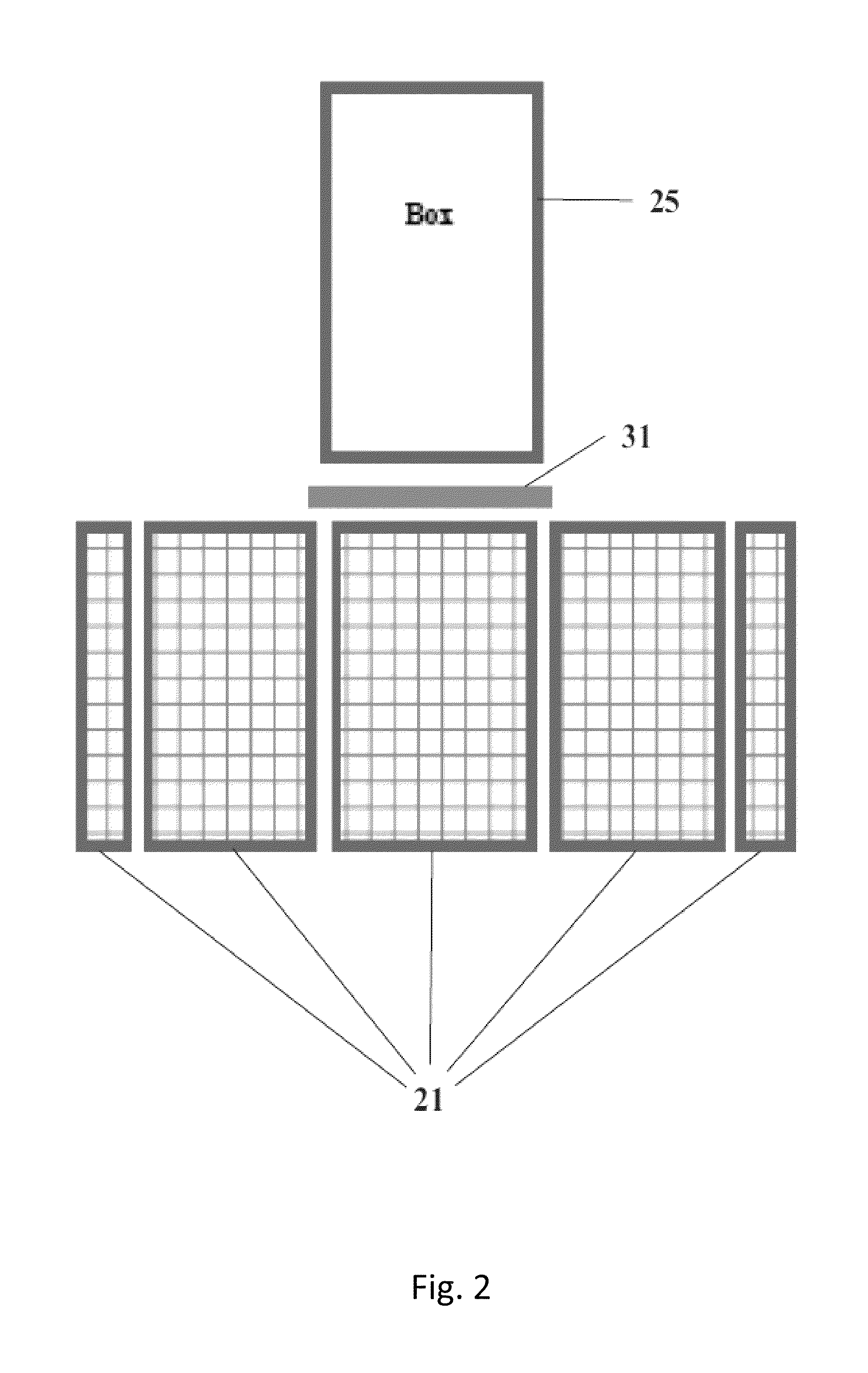
[0032]A conceptual design for a system to perform these operations is shown in FIGS. 1 and 2. A slight variation on the concept is shown in FIGS. 3 and 4. The overall conceptual design is discussed above, and a detailed discussion of the operation and the ancillary equipment that will be required is set out below.

[0033]In this embodiment, there are ten “monoliths” located in a decagon arrangement and which are located on a circular track. There are two circular / decagon assemblies associated with each process unit and they interact with each other (see FIGS. 1-4). Air is passed through the monoliths by induced draft fans located on the inner sides of the monoliths. At one location the monoliths are in a position adjacent to a single sealable chamber box, into which each monolith is inserted, as shown by vertically moving the bed out from the track, for processing (i.e. where they are heated to a temperature of not greater than 130 C., and more preferably not above 120 C., preferably ...


PUM

PropertyMeasurementUnit
temperatureaaaaaaaaaa

Abstract

A system for removing carbon dioxide from a carbon dioxide laden gas mixture, the system comprising two groups of carbon dioxide removal structures, each removal structure within each group comprising a porous solid mass substrate supported on the structure and a sorbent that is capable of adsorbing or binding to carbon dioxide, to remove carbon dioxide from a gas mixture, the sorbent being supported upon the surfaces of the porous mass substrate solid; an endless loop support for each of the groups of the removal structures, the endless loop support being so arranged as to move the support structures of each group along a closed curve while being exposed to a stream of the gas mixture; and a sealable regeneration box at one location along each of the endless loop supports, in which, when a porous solid mass substrate is sealed in place therein, carbon dioxide adsorbed upon the sorbent is stripped from the sorbent and the sorbent regenerated; each removal structural supporting a porous substrate in a position to be exposed to a flow of carbon dioxide laden gas mixture so as to allow for the removal of CO2 from the gas mixture; the number of removal structures to the number of regeneration boxes being directly determined by the ratio of the time to adsorb CO2, from a base level to desired level on the sorbent, to the time to strip the CO2 from the desired level back to the base level.

Description

[0001]This application claims the benefit of priority pursuant to 35 U.S.C. 119(e) from a U.S. Provisional Patent Application having Application No. 61 / 922,338 filed Dec. 31, 2013, the text of which is fully incorporated by reference herein as if repeated below.BACKGROUND[0002]The present invention relates to systems and methods for removing greenhouse gases from the atmosphere, and in particular to systems and methods for removing carbon dioxide from a stream of gas, including ambient air.[0003]As a further improvement to the system described in copending U.S. application Ser. No. 13 / 098,370, filed on Apr. 29, 2011, a suitable system and process is presented that it is now recognized can be utilized for a broader range of use than disclosed in that earlier application, especially when further modified. The disclosure of that copending application is incorporated by reference herein as if repeated in full, as modified by the new disclosure presented herein.[0004]There is much attent...

Claims


Application Information

Patent Timeline
Patent Type & Authority Applications(United States)
IPC IPC(8): B01D53/08
CPCB01D53/08B01D2257/504B01D2253/202B01D2252/204B01D2253/104B01D2253/106B01D2253/25B01D2259/4009B01D53/06B01D2253/342B01D2259/4067B01D2259/65B01J20/3204B01J20/327Y02C20/40
Inventor EISENBERGER, PETER
Owner GLOBAL THERMOSTAT OPERATIONS LLC
Why Eureka
Try Eureka