Eureka AIR delivers breakthrough ideas for toughest innovation challenges, trusted by R&D personnel around the world.

Contact-less power transfer

a technology of contact-less power and power transfer, which is applied in the direction of transformer/inductance magnetic core, electrochemical generator, core/yoke, etc., can solve the problems of saving the user the cost and inconvenience of regularly having to purchase new cells, the device becomes useless, and the loss of important data stored locally in the devi

Inactive Publication Date: 2006-04-13
PHILIPS IP VENTURES BV
View PDF4 Cites 87 Cited by
  • Summary
  • Abstract
  • Description
  • Claims
  • Application Information

AI Technical Summary

Benefits of technology

[0049] The at least one means for generating an electromagnetic field may be a coil, for example in the form of a length of wire or a printed strip, or may be in the form of a conductive plate of appropriate configuration, or may comprise any appropriate arrangement of conductors. A preferred material is copper, although other conductive materials, generally metals, may be used as appropriate. It is to be understood that the term “coil” is here intended to encompass any appropriate electrical conductor forming an electrical circuit through which current may flow and thus generate an electromagnetic field. In particular, the “coil” need not be wound about a core or former or the like, but may be a simple or complex loop or equivalent structure.
[0170] It is known in the art to drive coils using parallel or series resonant circuits. In series resonant circuits for example, the impedance of the coil and the capacitor are equal and opposite at resonance, hence the total impedance of the circuit is minimised and a maximum current flows through the primary coil. The secondary device is typically also tuned to the operating frequency to maximise the induced voltage or current.

Problems solved by technology

Many of today's portable devices incorporate “secondary” power cells which can be recharged, saving the user the cost and inconvenience of regularly having to purchase new cells.
There are a number of problems associated with conventional means of powering or charging these devices:
These adaptors and chargers often require users to plug a small connector into the device or to place the device with accurate alignment into a stand causing inconvenience.
If users fail to plug or place their device into a charger and it runs out of power, the device becomes useless and important data stored locally in the device might even be lost.
In addition, most adaptors and chargers have to be plugged into mains sockets and hence if several are used together, they take up space in plug strips and create a messy and confusing tangle of wires.
Besides the above problems with conventional methods of recharging devices, there are also practical problems associated with devices having an open electrical contact.
For example, devices cannot be used in wet environments due to the possibility of corroding or shorting out the contacts and also they cannot be used in flammable gaseous environments due to the possibility of creating electrical sparks.
However such chargers still suffer from all other problems as described above.
The adaptors are still only designed specifically for a certain make and model of device and are still only capable of charging one device at a time.
Whilst these universal chargers eliminate the need for having different chargers for different devices, they create even more inconvenience for the user in the sense that the battery packs first need to be removed, then the charger needs to be adjusted and the battery pack needs to be accurately positioned in or relative to the charger.
Although theoretically feasible, this method suffers from a number of drawbacks.
Firstly, the intensity of electromagnetic emissions is governed by regulatory limits.
This means that this method can only support power transfer at a limited rate.
For example, data stored on credit cards maybe destroyed and objects made of metal will have induced therein eddy currents generating undesired heating effects.
Although this method provides a solution to the problems previously listed, it does so in a complicated and costly way.
The cost associated with a multiple-coil system would severely limit the commercial applications of this concept.
Non-uniform field distribution is also a drawback.
While this scheme also offers freedom of movement of the device, it has the disadvantages of needing a complex secondary device, having a fixed resolution, and having poor coupling because the return flux path is through air.
None of the prior art solutions can satisfactorily address all of the problems that have been described.
Primary cells, or batteries of them, must be disposed of once used, which is expensive and environmentally unfriendly.
It is inconvenient for the user to have to either remove cells from the device for recharging, or to have to plug the device into an external power source for recharging in-situ.

Method used


Image

  • Contact-less power transfer
  • Contact-less power transfer
  • Contact-less power transfer

Examples


Embodiment Construction

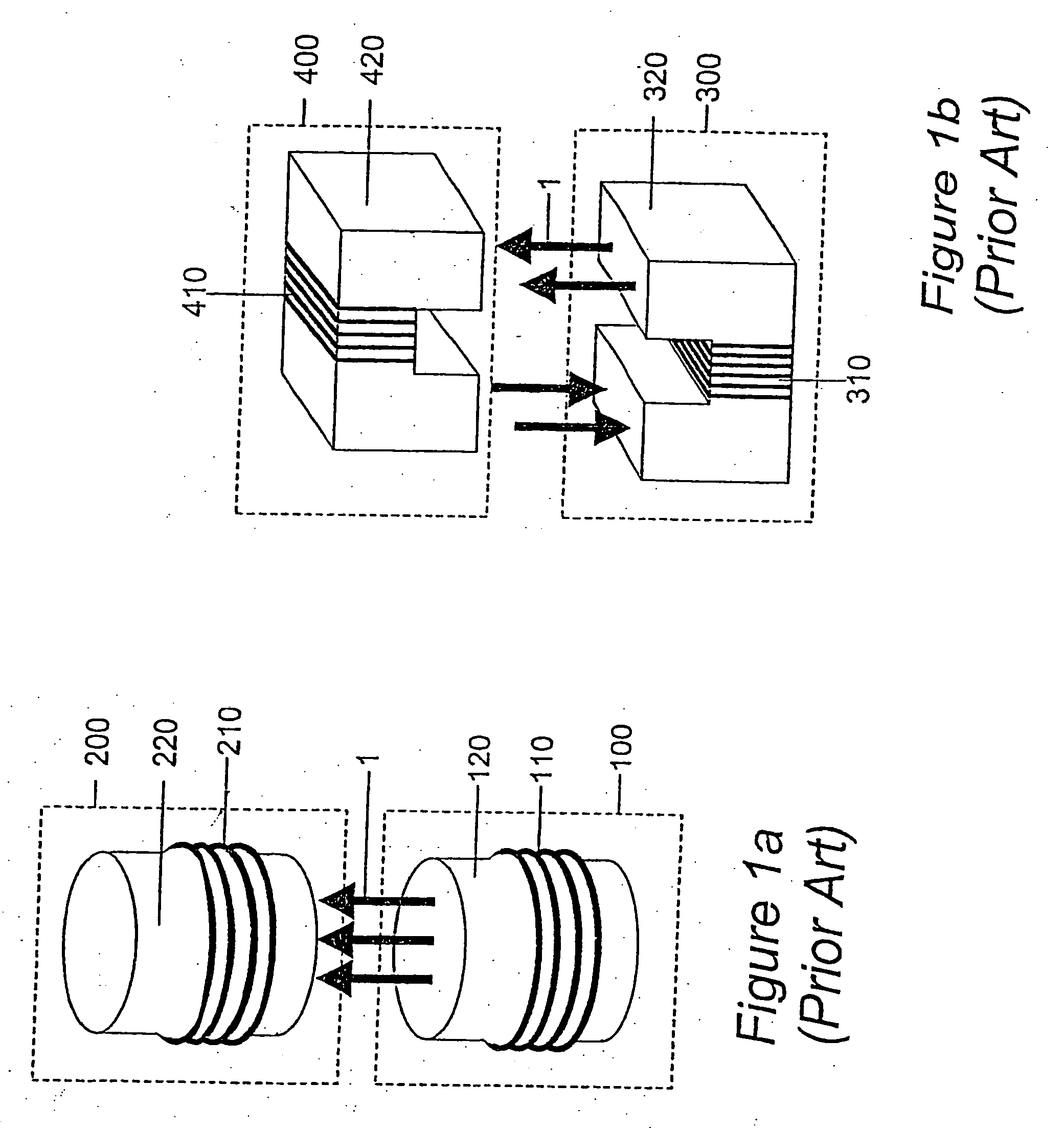
[0206] Referring firstly to FIG. 1, there is shown two examples of prior art contact-less power transfer systems which both require accurate alignment of a primary unit and a secondary device. This embodiment is typically used in electric toothbrush or mobile phone chargers.

[0207]FIG. 1a shows a primary magnetic unit 100 and a secondary magnetic unit 200. On the primary side, a coil 110 is wound around a magnetic core 120 such as ferrite. Similarly, the secondary side consists of a coil 210 wound around another magnetic core 220. In operation, an alternating current flows in to the primary coil 110 and generates lines of flux 1. When a secondary magnetic unit 200 is placed such that it is axially aligned with the primary magnetic unit 100, the flux 1 will couple from the primary into the secondary, inducing a voltage across the secondary coil 210.

[0208]FIG. 1b shows a split transformer. The primary magnetic unit 300 consists of a U-shaped core 320 with a coil 310 wound around it. ...


PUM

PropertyMeasurementUnit
angleaaaaaaaaaa
core thicknessaaaaaaaaaa
thicknessaaaaaaaaaa

Abstract

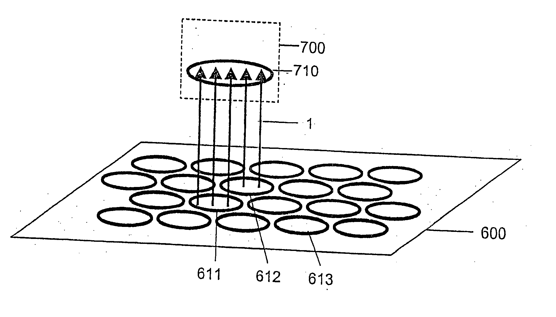
There is disclosed a system and method for transferring power without requiring direct electrical conductive contacts. There is provided a primary unit having a power supply and a substantially laminar charging surface having at least one conductor that generates an electromagnetic field when a current flows therethrough and having an charging area defined within a perimeter of the surface, the at least one conductor being arranged such that electromagnetic field lines generated by the at least one conductor are substantially parallel to the plane of the surface or at least subtend an angle of 45° or less to the surface within the charging area; and at least one secondary device including at least one conductor that may be wound about a core. Because the electromagnetic field is spread over the charging area and is generally parallel or near-parallel thereto, coupling with flat secondary devices such as mobile telephones and the like is significantly improved in various orientations thereof.

Description

CROSS REFERENCE TO RELATED APPLICATIONS [0001] This application is a Continuation of application Ser. No. 11 / 000,035, filed on Dec. 1, 2004, which is itself a Division of application Ser. No. 10 / 514,046, filed on Feb. 28, 2005. [0002] The present application claims priority from UK patent applications numbers 0210886.8 of 13th May 2002, 0213024.3 of 7th Jun. 2002, 0225006.6 of 28th Oct. 2002 and 0228425.5 of 6th Dec. 2002, as well as from U.S. patent application Ser. No. 10 / 326,571 of 20th Dec. 2002. The full contents of all of these prior patent applications is hereby incorporated into the present application by reference.FIELD BACKGROUND OF THE INVENTION [0003] This invention relates to a new apparatus and method for transferring power in a contact-less fashion. BACKGROUND OF THE INVENTION [0004] Many of today's portable devices incorporate “secondary” power cells which can be recharged, saving the user the cost and inconvenience of regularly having to purchase new cells. Example ...

Claims


Application Information

Patent Timeline
Patent Type & Authority Applications(United States)
IPC IPC(8): H02J7/00H01F27/28
CPCH01F38/14H02J5/005H01M10/46Y02E60/10H02J50/90H02J50/12H02J50/70H02J7/00034H01F3/02H01F27/25H01F27/2804H01F41/0226H01F41/0233H02J50/10H01F27/245H04B5/79H02J7/00
Inventor CHENG, LILY KA-LAIHAY, JAMES WESTWOODBEART, PILGRIM GILES WILLIAM
Owner PHILIPS IP VENTURES BV
Why Eureka
Eureka Blog
Learn More