Socket with a Communication System

a communication system and socket technology, applied in the direction of line-transmission details, two-part coupling devices, coupling device connections, etc., can solve the problems of inability to flush mount, inconvenient installation, and significant limitations of said devices

Inactive Publication Date: 2019-05-09
SIMON SA
View PDF15 Cites 1 Cited by
  • Summary
  • Abstract
  • Description
  • Claims
  • Application Information

AI Technical Summary

Problems solved by technology

However, said devices have some significant limitations.
One of the main limitations is the relationship between the amperage at which they operate and their size, which makes it impossible to integrate them flush mounted in a wall.
The devices of the state of the art, in order to overcome these drawbacks, reduce the amperage, which means that they cannot be flush mounted, or they are very large and cannot be integrated into a universal flush-mountable box and the solution used in the state of the art is to make them external.

Method used


Image

  • Socket with a Communication System
  • Socket with a Communication System
  • Socket with a Communication System

Examples


Embodiment Construction

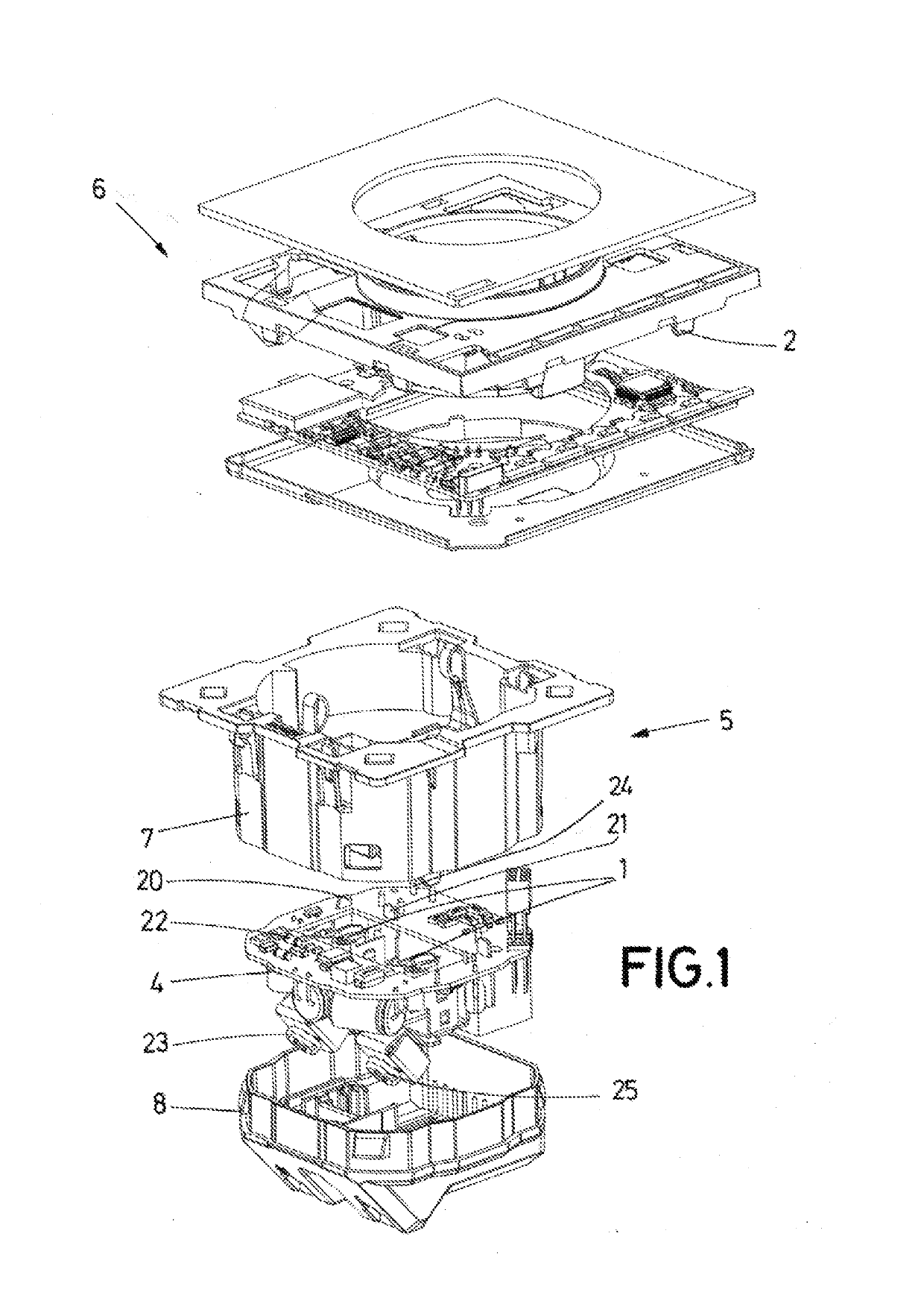
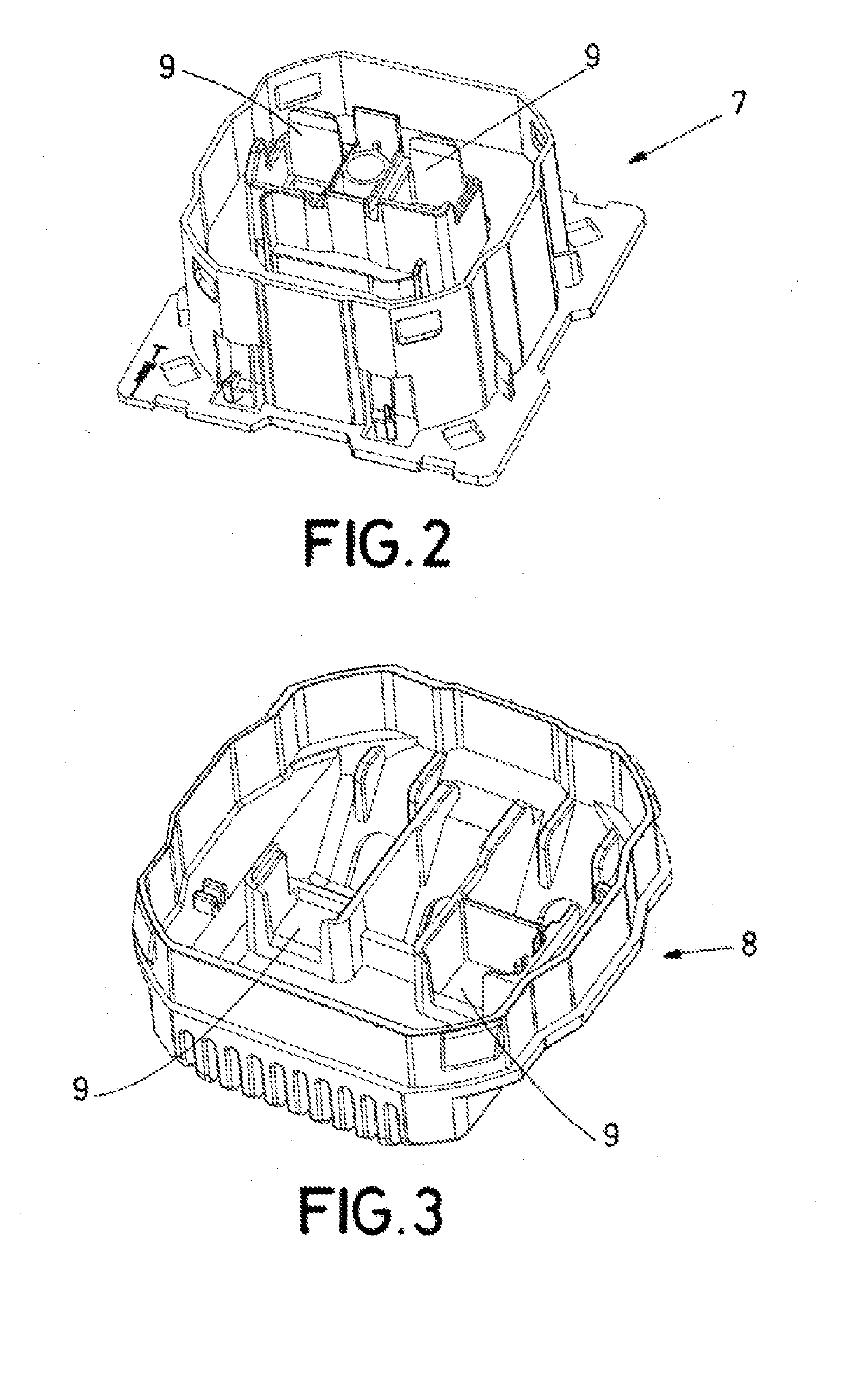
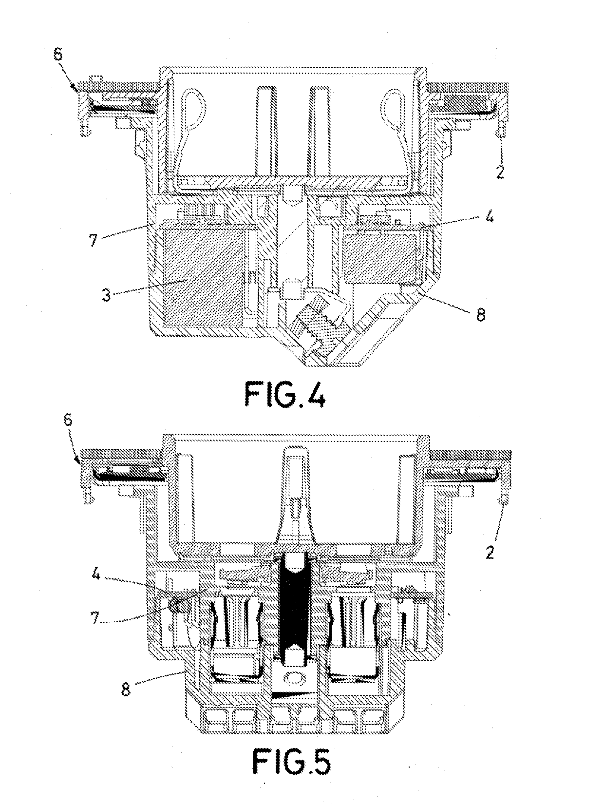
[0008]The present invention proposes a socket with a communication system. The key of this socket is that it is flush-mountable and that the communication system is arranged in the housing of the socket. Said housing preferably comprises a base and a cover of the base and the base of the socket is completely housed in a universal box flush mounted in the wall into which it is installed and is connected directly to the electrical grid by means of connection terminals.

[0009]This socket enables the problems described of the state of the art to be solved since it enables the installation thereof with a direct connection to the electrical grid and it is flush mounted in the wall. To do so, the socket has been designed such that all the components it comprises are housed in the housing of the socket, from which the terminals necessary for connecting to the electrical grid protrude.

[0010]When the socket is flush mounted in the wall, only the outer face of the cover of the socket, which is ...


PUM


Abstract

Socket with a communication system that is flush-mountable and comprises at least one housing with at least one communication system, a control circuit and a connection system of the socket, and a receptacle for a plug to be connected in the socket, and the connection system of the socket comprises terminals (23, 25) to connect directly to the electrical grid. The socket has been designed such that all the components it comprises are housed in the housing of the socket, from which only the terminals necessary for connecting to the electrical grid protrude.

Description

OBJECT OF THE INVENTION[0001]The present invention falls within the technical field of coupling devices intended to receive a plug. More specifically, it describes a flush-mountable socket comprising a communication system for communicating with other devices.BACKGROUND OF THE INVENTION[0002]Smart connection solutions are known in the state of the art. These are devices that comprise communication systems in the inside thereof configured to enable a user to control the turning on and off of thereof, control the current intensity passing therethrough, etc.[0003]However, said devices have some significant limitations. One of the main limitations is the relationship between the amperage at which they operate and their size, which makes it impossible to integrate them flush mounted in a wall.[0004]The devices that are flush mounted in a wall must work according to the installation rules of each country or region between 10 A and 16 A, and the devices of the state of the art that work at...

Claims


Application Information

Patent Timeline
Patent Type & Authority Applications(United States)
IPC IPC(8): H01R13/703H01R13/506H04W88/08H01R24/78
CPCH01R13/7038H01R13/506H04W88/08H01R24/78H01R13/66H04B3/02
Inventor MIRANDA JOVE, HECTOROBIOL BAYA, JORGE
Owner SIMON SA
Why Eureka
Try Eureka