Printer and printing control method

Inactive Publication Date: 2006-04-13
SEIKO EPSON CORP
View PDF3 Cites 9 Cited by
  • Summary
  • Abstract
  • Description
  • Claims
  • Application Information

AI Technical Summary

Benefits of technology

[0013] The invention has been made in view of the above circumstances, and advantages thereof are to provide a printer and a printing control method in which, to print a printing object provided with a notch, ejection of ink droplets can be properly controlled to prevent contamination of the top surface of a guide member, to provide a printer and a drive control method that ca

Problems solved by technology

Consequently, when reaching between the transport roller pair, the rear end of the thick printing object is biased by the spring toward a discharge side, thus unpredictably increasing the speed of transport of the printing object.
This is the phenomenon called “kicking”, and there arises the problem in which the occurrence of this phenomenon results in nonuniform printing on the printing object, thus preventing proper printing.
Therefore, the existence of the notches in the photo stand paper makes it difficult to detect the rear end side of the photo stand paper.
However, the existence of the notches prevents the rear end of the photo stand paper from being accurately detected using the paper detector.
Besides, if, due to the existence of the notches, it is determined that no photo stand paper exists, there is the possibility of damaging a printhead.
And, in this state, upon movement of the carriage, the printhead sometimes comes into contact with the photo stand paper, thus causing the damage of the printhead.
However, in this case, it becomes more difficult to accurately detect the rear end of the photo stand paper.
Besides, in the current printer, the paper detector is disposed on the side in the main scan direction on which the cleaning mechanism exists, so that it is difficult to change a layout of the paper detector in the main scan direction, because of the relationship with the other configurations.
Therefore, to print the photo stand paper, the so-called “kicking”

Method used


Image

  • Printer and printing control method
  • Printer and printing control method
  • Printer and printing control method

Examples


first embodiment

[0197] Besides, the control programs for controlling the printer 10, data necessary for processes, and the like are stored in the ROM 72. In the invention, a drive control program and the like responsive to the kind of the printing object 12 are stored in the ROM 72. This drive control program enables the control and driving of the PF motor 25 which are based on detection of the PW sensor 64 and correspond to a to-be-described flowchart shown in FIG. 9. Besides, the I / F circuit 75 incorporates a parallel interface circuit and can receive a print signal supplied from a computer 90 via a connector 91.

[0198] The RAM 73 is a memory that temporarily stores, for example, a program being executed or data being calculated by the CPU 71. Besides, the nonvolatile memory 80 is a memory for storing various data that need be held even after the inkjet printer 10 is powered off.

[0199] Besides, the DC unit 76 is a control circuit for controlling the speed of the PF motor 25 and CR motor 55 that a...

second embodiment

[0241] The second embodiment will now be described with reference to FIG. 10.

[0242] In the second embodiment, a drive control program responsive to the kind of the printing object 12 is stored in the ROM 72. This drive control program enables the control and driving of the PF motor 25 which are based on detection of the PW sensor 64 and correspond to a to-be-described flowchart shown in FIG. 10.

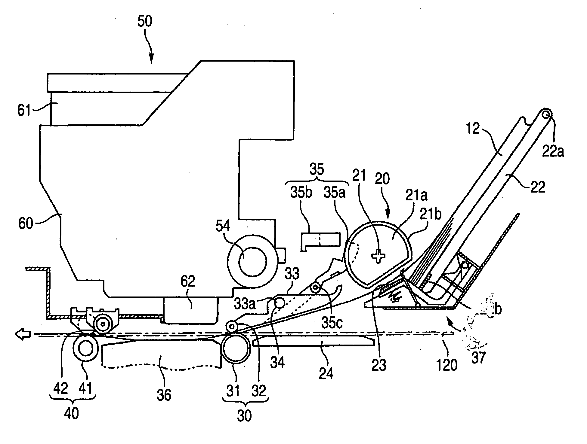
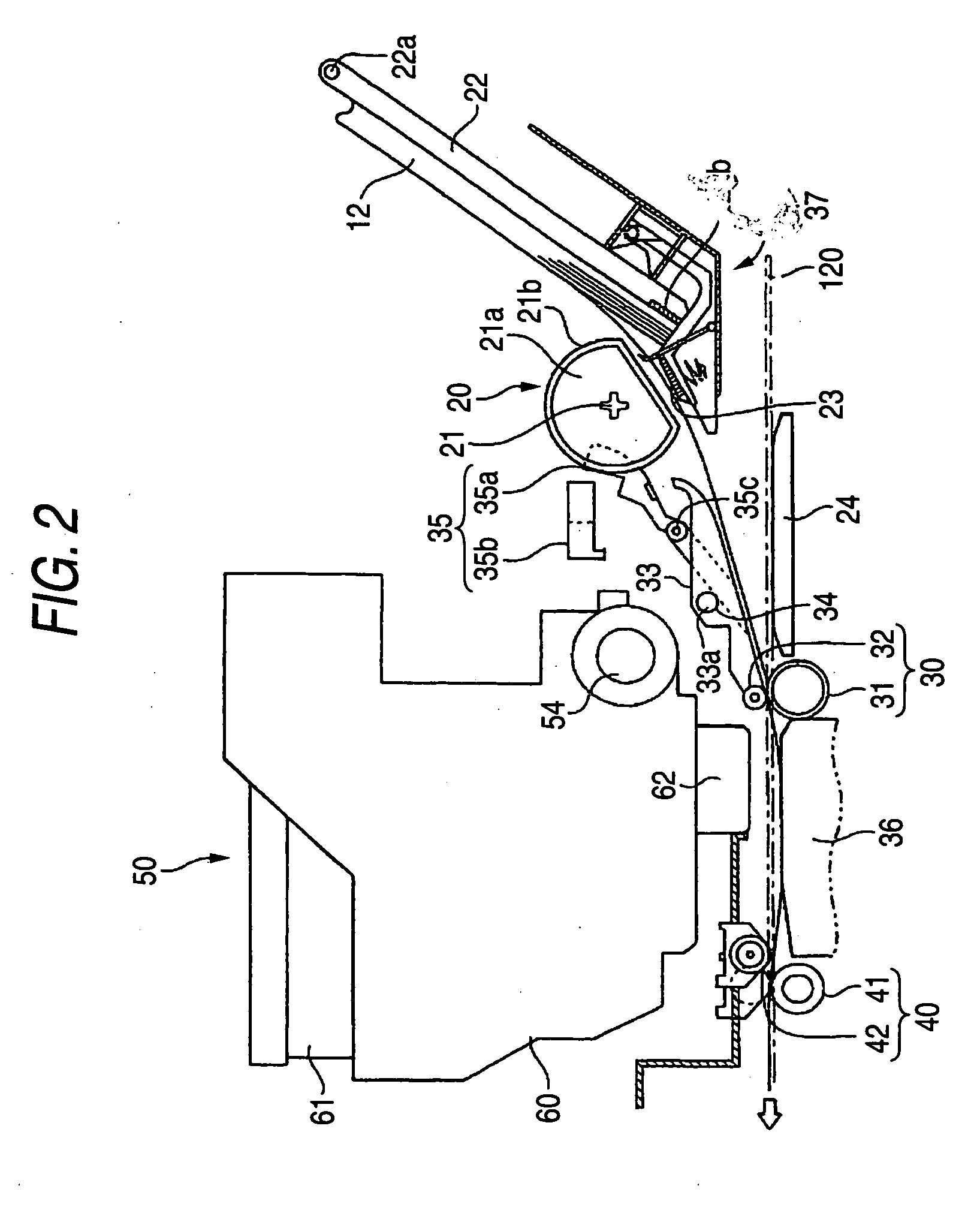
[0243] Step T10: When a user sets the photo stand paper 120 and sends a print command, a paper feed operation of feeding the photo stand paper 120 is started. In this case, the user inserts the photo stand paper 120, for example, from the opening 37. Then, by a transport operation of the PF motor 25, the photo stand paper 120 reaches the opening 37, and subsequently the front end thereof on the discharge side is nipped by the PF roller pair 30. And, the PF drive roller 31 is driven by the PF motor 25, thereby transporting the photo stand paper 120 toward the paper discharge side.

[0244] Besi...

third embodiment

[0269] The third embodiment will now be described.

[0270] In a third embodiment, a drive control program, a correction value A, and the like responsive to the kind of the printing object 12 are stored in the ROM 72. This drive control program enables the control and driving of the PF motor 25 which are based on detection of the PW sensor 64 and correspond to to-be-described flowcharts shown in FIGS. 11 and 12.

[0271] There will first be described the method of correcting a general printing object other than the photo stand paper 120. To describe a correction value, the control section 70 corrects the amount of the printing object 12 transported, using three correction values A, B, and C serving as the correction information. These correction values are for correcting the error (hereinafter called the “transport error”) between a theoretical amount of the printing object 12 transported (paper transport amount) and an actual amount thereof transported.

[0272] The correction value A cor...


PUM


Abstract

A printing device has a first part and a second part and prints an image on a medium adapted to be transported from the first part to the second part in a transport direction and having a notch disposed at a back end portion in the transport direction. A printing head is disposed between the first part and the second part and is adapted to eject ink to the medium. A first driver is operable to drive one of a pair of rollers adapted to nip the medium to form a nip portion therebetween so that the rollers transport the medium from the first part to the second part in the transport direction. A second driver is operable to drive the printing head so that the printing head ejects the ink to the medium. An anticipator anticipates a location of the back and portion. A controller is operable to control the second driver so as to cause the printing head not to eject the ink in association with the location anticipated by the anticipator.

Description

BACKGROUND OF THE INVENTION [0001] The present invention relates to a printer and a printing control method. [0002] In printers including an inkjet one, types capable of performing a variety of printing are prevailing. Among such types of printers, there exists a type capable of performing so-called four-side margin-less printing. Also, such types of printers normally has a transport roller pair and a paper discharge roller pair, which each include a drive roller and a driven roller, wherein a printing object is transported nipped between both rollers of each of the roller pairs. In this configuration, normally, at least one of the drive and driven rollers of each of the roller pairs is connected to a spring, and a biasing force is applied by the springs to the printing object. [0003] In the meantime, in performing the margin-less printing on a thick printing object, the thick printing object is often affected by the phenomenon of so-called “kicking”. This “kicking” occurs as the re...

Claims


Application Information

Patent Timeline
IPC IPC(8): B41J2/01
CPCB41J11/0065B41J11/06
Inventor TAKEISHI, TETSUJIKUGIMACHI, HISATAKA
Owner SEIKO EPSON CORP
Why Eureka
Try Eureka