Secam color difference signal processing method
a signal processing and color difference technology, applied in the field of video signal processing, can solve the problem of line flicker at half the frame rate, and achieve the effect of reducing spatial color noise and flicker
- Summary
- Abstract
- Description
- Claims
- Application Information
AI Technical Summary
Benefits of technology
Problems solved by technology
Method used
Image
Examples
first embodiment
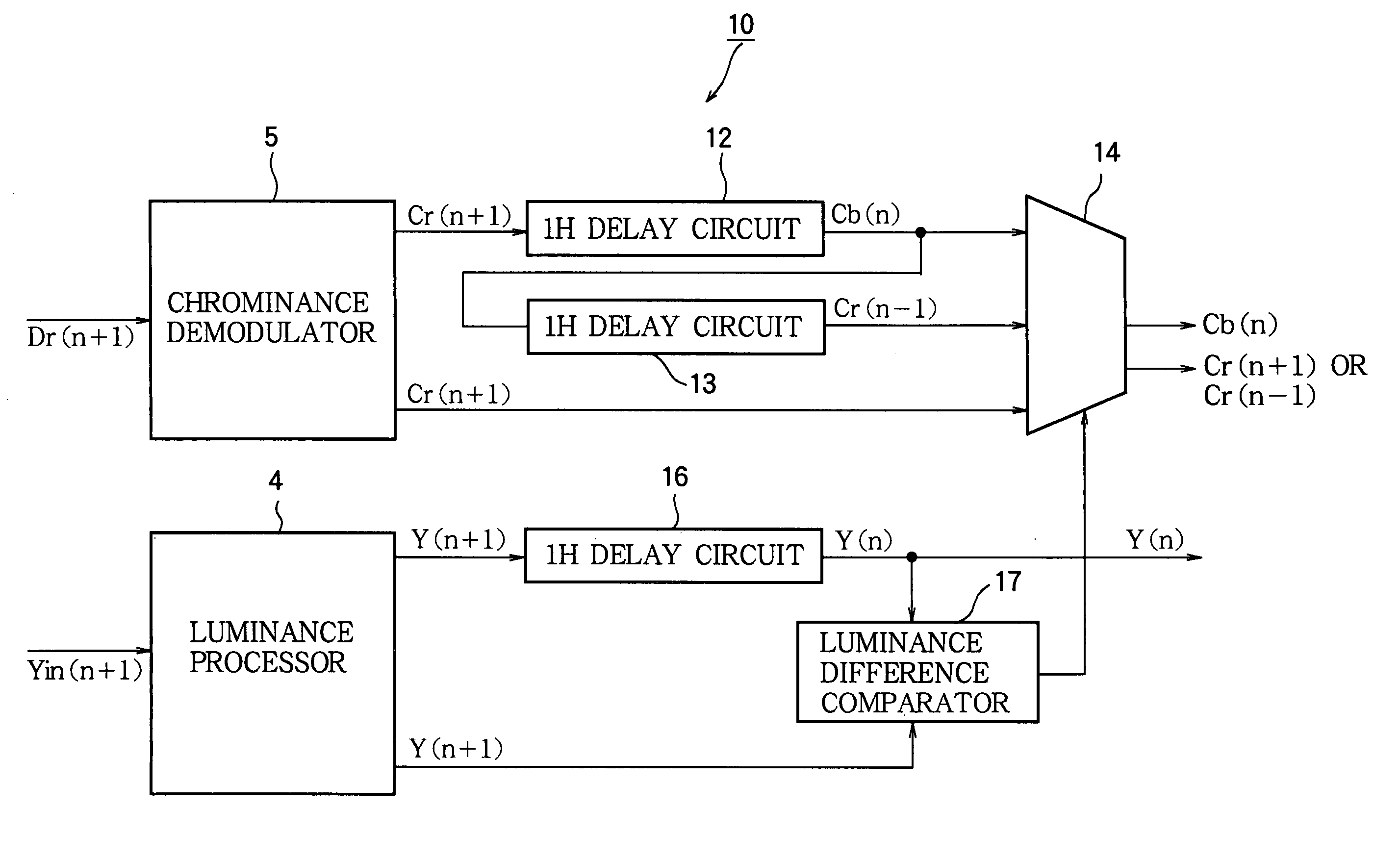
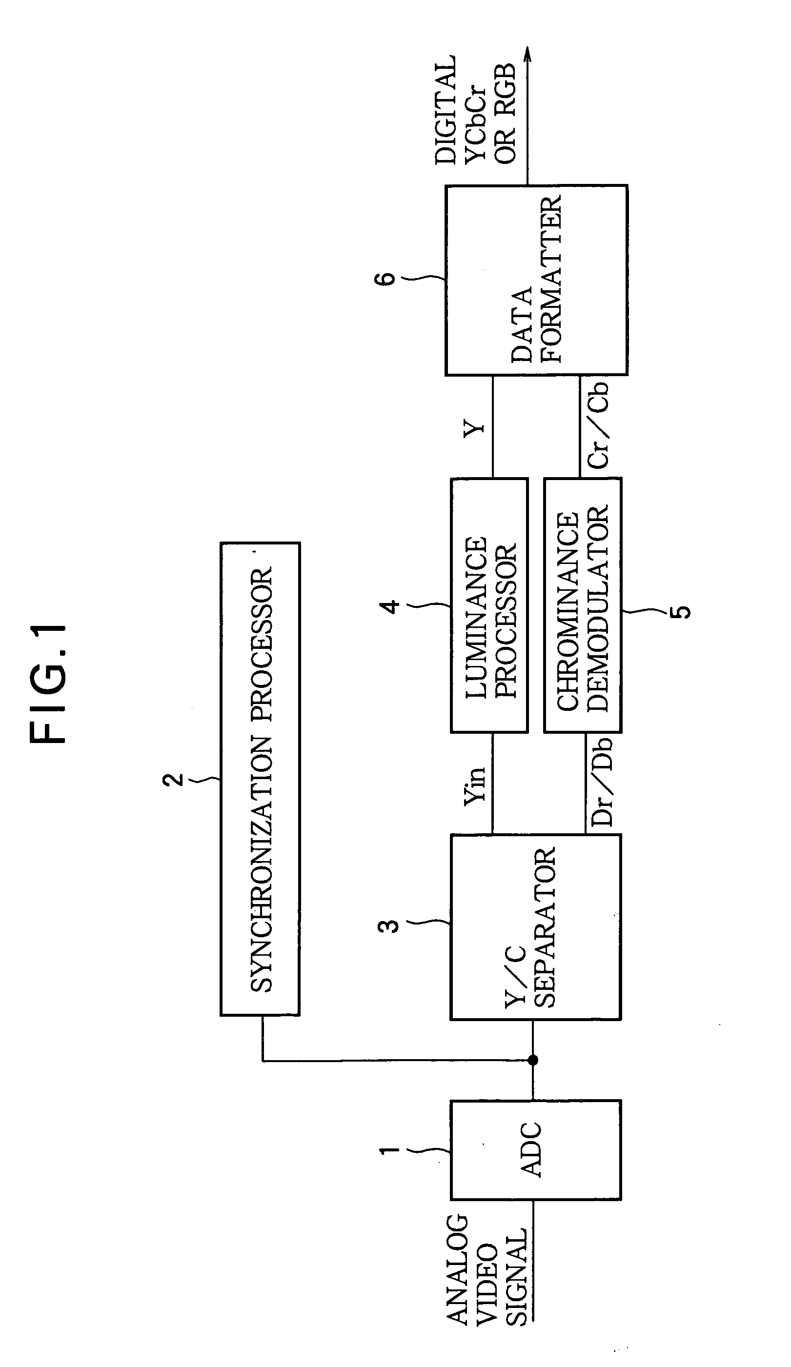
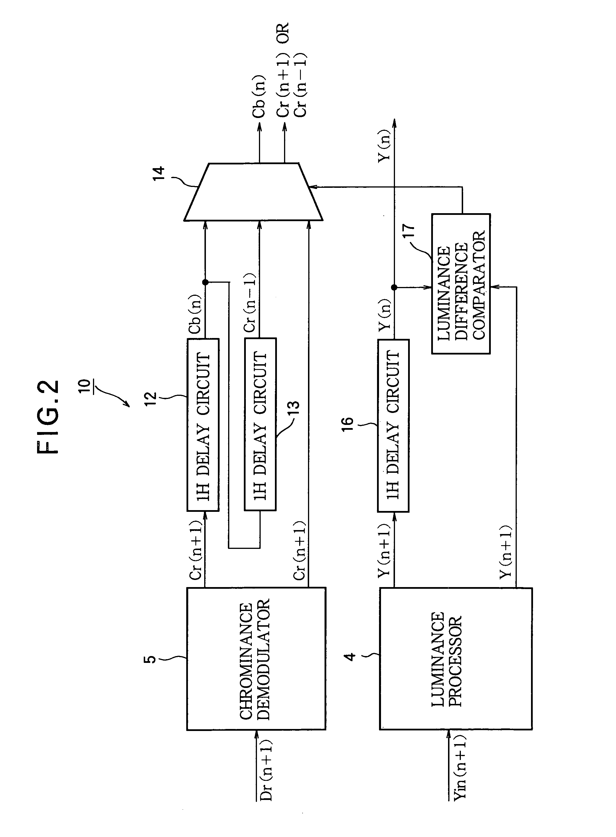
[0028]FIG. 2 shows a SECAM signal data processing circuit 10 that includes the luminance processor 4, the chrominance demodulator 5, and part of the data formatter 6 in FIG. 1 in a first embodiment of the invention. The part of the data processing circuit 10 disposed in the data formatter includes a cascaded pair of 1H delay circuits 12, 13, a selector 14, another 1H delay circuit 16, and a luminance difference comparator 17. This circuit 10 outputs luminance and color difference data for a given line n while receiving the digitized SECAM signal for the next line (n+1).
[0029] The chrominance demodulator 5 demodulates the separated chrominance signal to obtain color difference data. As an example, the chrominance demodulator 5 is shown as receiving a chrominance signal Dr(n+1) for line (n+1) when the chrominance signal for this line encodes red color difference information. The color difference data signal output from the chrominance demodulator 5 is accordingly denoted Cr(n+1).
[00...
second embodiment
[0039]FIG. 3 shows a SECAM signal data processing circuit 20 that includes the luminance processor 4, the chrominance demodulator 5, and part of the data formatter 6 in FIG. 1 in a second embodiment of the invention. The part of this data processing circuit 20 disposed in the data formatter 6 in FIG. 1 includes the 1H delay circuits 12, 13, 16 and luminance difference comparator 17 described in the first embodiment, a different selector 24, and an averager 28.
[0040] The averager 28 adds the outputs of the chrominance demodulator 5 and 1H delay circuit 13 and right-shifts the resulting sum by one bit to obtain a color difference signal representing the average of the color difference signal in the input line and the color difference signal two lines before. In the example shown, these two signals are red color difference signals Cr(n+1) and Cr(n−1) and their average is {Cr(n+1)+Cr(n−1)} / 2. When the control signal received from the luminance difference comparator 17 indicates that th...
PUM
 Abstract
Description
Claims
Application Information
 - R&D
- Intellectual Property
- Life Sciences
- Materials
- Tech Scout
- Unparalleled Data Quality
- Higher Quality Content
- 60% Fewer Hallucinations
Browse by: Latest US Patents, China's latest patents, Technical Efficacy Thesaurus, Application Domain, Technology Topic, Popular Technical Reports.
© 2025 PatSnap. All rights reserved.Legal|Privacy policy|Modern Slavery Act Transparency Statement|Sitemap|About US| Contact US: help@patsnap.com


