Disaster system control method and disaster system control apparatus

a control method and disaster system technology, applied in the field of disaster system control method and disaster system control apparatus, can solve the problems of affecting the ability of the affected person to input information, and affecting the ability of the affected person to initiate information inpu

Inactive Publication Date: 2006-04-13
FUJITSU LTD
View PDF10 Cites 53 Cited by
  • Summary
  • Abstract
  • Description
  • Claims
  • Application Information

AI Technical Summary

Benefits of technology

[0026] Thus, it becomes possible to preferentially transfer packet calls which can transmit more information than voice calls or the like. By performing a transmission / reception between the disaster system center and e.g. a mobile terminal within a disaster occurrence area by the packet calls, an information collection route can be secured, and a call congestion state upon disaster can be reduced. Namely, it becomes possible to promptly transmit / receive disaster status or situation information upon disaster occurrence between the disaster monitoring person and the afflicted people within the disaster occurrence area.
[0097] Thus, it becomes possible to prevent the download of the application for disaster by a malicious download request.

Problems solved by technology

However, under the communication line restrained status, information discard, delay, or the like occurs, so that a difficulty of information collection is anticipated.
Also, since a recording time is limited to several seconds in an emergency messaging service, it is very difficult for the afflicted person to input information by which a detailed status as to whether the afflicted person is seriously / slightly injured or the like can be recognized.
Also, since a restraint on communication lines giving a preference to an emergency communication upon disaster occurrence is not made, there is a possibility of disabling an emergency communication due to congestion.

Method used


Image

  • Disaster system control method and disaster system control apparatus
  • Disaster system control method and disaster system control apparatus
  • Disaster system control method and disaster system control apparatus

Examples


Embodiment Construction

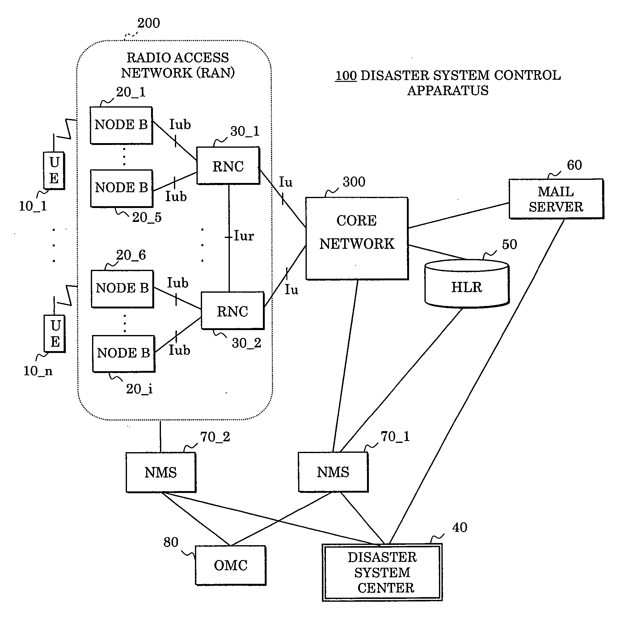
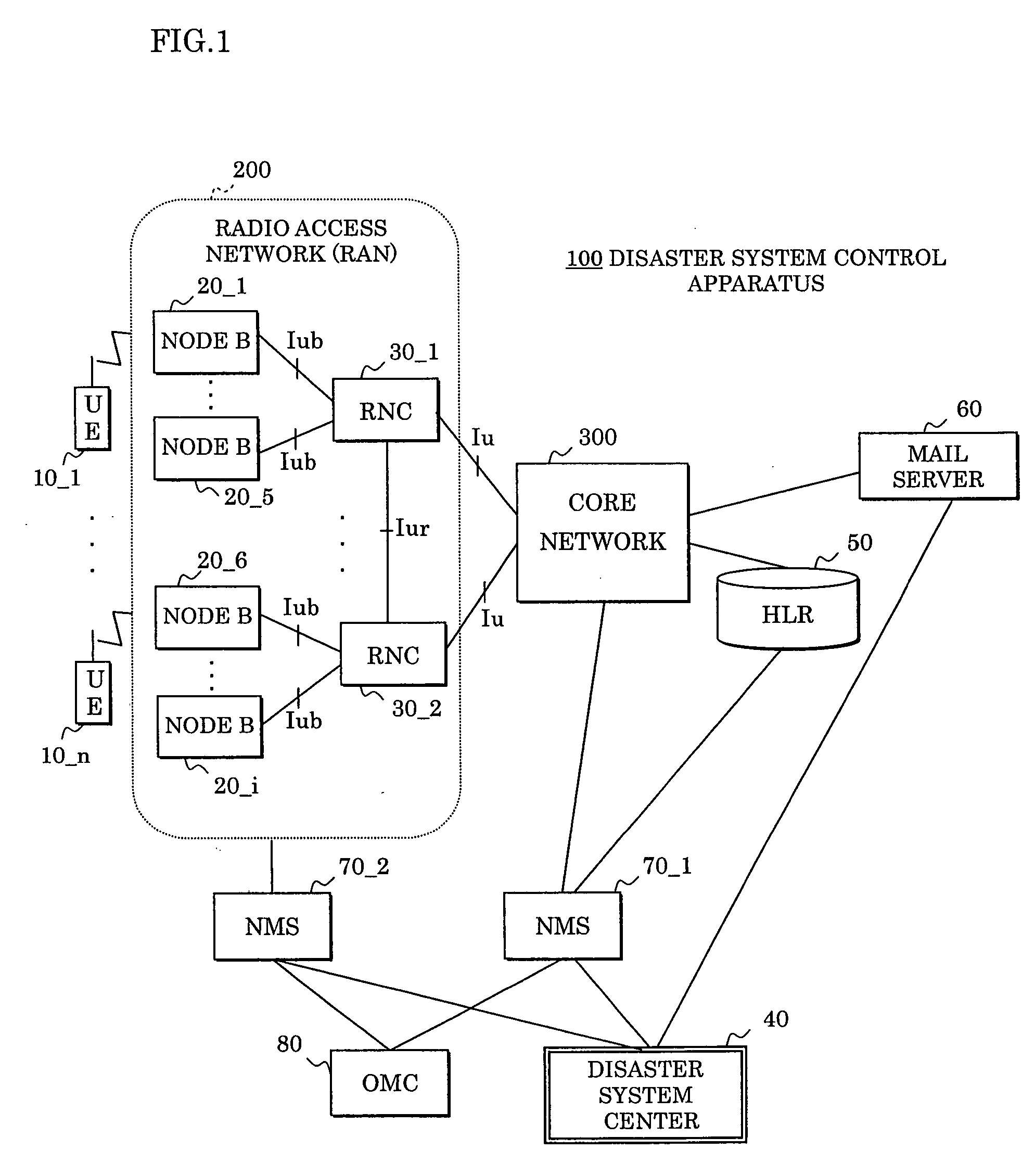
[0124]FIG. 1 shows an embodiment of a disaster system control apparatus 100 which is one embodiment of a disaster system control method according to the present invention. This disaster system control apparatus 100 is composed of a disaster system center (hereinafter, occasionally abbreviated as DS) 40, a home location register (hereinafter, occasionally abbreviated as HLR) 50, a mail server 60, a core network 300, a radio access network (hereinafter, occasionally abbreviated as RAN) 200, and user equipments (hereinafter, occasionally abbreviated as UE) or mobile stations 10_1-10_n (hereinafter, occasionally represented by a reference numeral 10).

[0125] The RAN 200 is provided with radio network controllers (hereinafter, occasionally abbreviated as RNC) 30_1 and 30_2 (hereinafter, occasionally represented by a reference numeral 30), and nodes B20_1-B20_i (hereinafter, occasionally represented by a reference numeral 20). This node B20 is a logical node performing a radio transmissio...


PUM


Abstract

In a disaster system control method and apparatus transmitting disaster status information through a mobile communication network or a fixed communication network, in order to promptly transmit / receive disaster status information at a time of a disaster occurrence between a disaster monitoring person and afflicted people within a disaster occurrence area, a bandwidth control apparatus assigns a bandwidth for a packet call in preference to other calls, a mobile terminal installs an application for disaster thereon for transmitting / receiving disaster status information between a disaster system center and the mobile terminal itself, and the disaster system center provides the mobile terminal within a disaster occurrence area with an application for disaster startup mail to start up the application for disaster.

Description

CROSS-REFERENCE TO RELATED APPLICATION [0001] This application is a continuation of International Application PCT / JP03 / 08546 filed on Jul. 4, 2003, the contents of which are herein wholly incorporated by reference.BACKGROUND OF THE INVENTION [0002] 1. Field of the Invention [0003] The present invention relates to a disaster system control method and a disaster system control apparatus, and in particular to a disaster system control method and a disaster system control apparatus transmitting disaster information through a mobile communication network or a fixed communication network. [0004] Together with a recent sophisticated development in communication technologies, not only in the mobile communication network but also the fixed communication network, communication means have increased their operating speed, have been multimedialized, and have become more and more important as means for exchanging information. When a large-scale disaster such as an extensive earthquake and fire oc...

Claims


Application Information

Patent Timeline
Patent Type & Authority Applications(United States)
IPC IPC(8): H04M11/04H04W8/10H04W28/20H04W4/90
CPCH04L12/1881H04L12/1895H04L12/5895H04L51/38H04M11/04H04W4/22H04W8/10H04W28/20H04W76/007H04W76/50H04W4/90H04L51/58
Inventor HIROUCHI, KIYOSHIITOH, YAYOIKAKIZAKI, NAOYUKIKAWAMURA, SAIKIABE, SATORUTAKEDA, YOSHIKAZUSUZUKI, TAKAHITOYOKOYAMA, HIROKI
Owner FUJITSU LTD
Why Eureka
Try Eureka