Self diverting matrix acid

a matrix acid, self-distributing technology, applied in the direction of folding cabinets, borehole/well accessories, cabinets, etc., can solve the problem of high price of surfactants

Active Publication Date: 2006-04-20
SCHLUMBERGER TECH CORP
View PDF38 Cites 36 Cited by
  • Summary
  • Abstract
  • Description
  • Claims
  • Application Information

AI Technical Summary

Problems solved by technology

Some of these systems are polymer-based; polymers may damage formations.
Other systems are based on viscoelastic surfactants (VES's) that are much cleaner; however, the existing VES systems require that the initial fluid contain sufficient surfactant to form a gel, and surfactants may be expensive.

Method used


Image

  • Self diverting matrix acid
  • Self diverting matrix acid
  • Self diverting matrix acid

Examples


examples

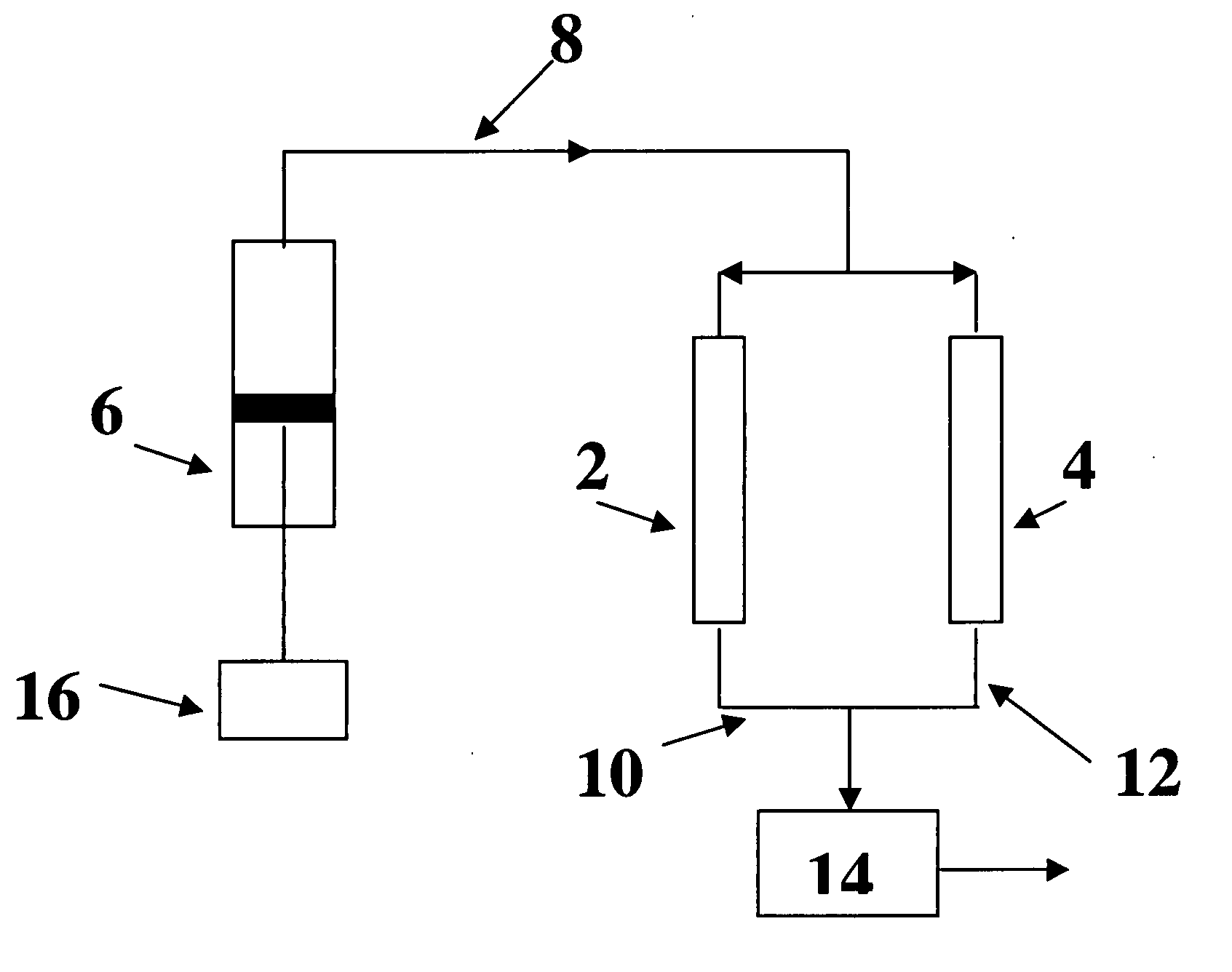
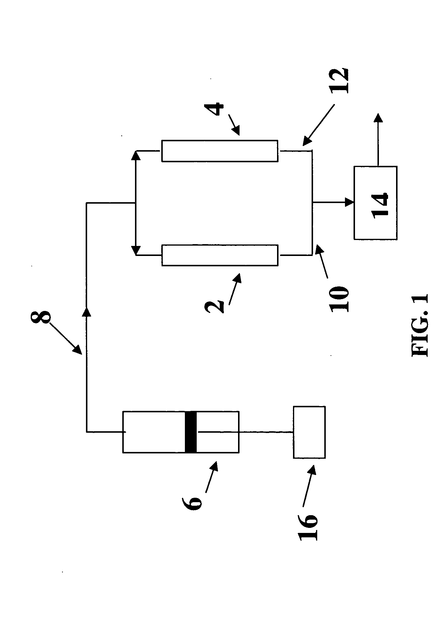
[0027] The VES / acid systems were tested for diverting capability using a dual core apparatus. A schematic of the apparatus used is shown in FIG. 1. The apparatus consists of two cores [2] and [4] in holders, a high permeability core and a low permeability core. The two cores were connected to an accumulator [6] containing acid that was displaced by a piston into a single fluid line [8] connected to the two core holders. The exit fluid lines of the core holders, [10] and [12], were connected to a backpressure regulator [14] that was maintained at 1200 psi (8.27 MPa). Acid was injected into the cores at a constant injection rate (2.5 ml / mn for most cases) until it broke through one of the cores. Unless stated otherwise, the acid always broke through the high permeability core. The effectiveness of the acid in diverting the fluid to the low permeability zone was determined by measuring the length of the wormhole formed in the low permeability core. Laboratory tests were conducted using...


PUM


Abstract

A method is described for treating a subterranean formation with a low viscosity fluid system that contains a viscoelastic surfactant at a concentration too low to viscosify the fluid, but that is concentrated in the formation so that the fluid system gels. The fluid optionally contains a formation-dissolving agent. The fluid is used in matrix acidizing, acid fracturing, and diversion.

Description

BACKGROUND OF THE INVENTION [0001] This invention relates to an acidic fluid that increases in viscosity as it is pumped into a subterranean formation. More particularly, it relates to a fluid system—that contains a concentration of a viscoelastic surfactant that is initially insufficient to cause the fluid to gel—that gels as the fluid flows through a permeable subterranean formation. Most particularly it relates to a method of treating a subterranean formation with such a fluid system. [0002] In many oilfield operations there are occasions when it is desirable to pump a low viscosity fluid that becomes more viscous after it has been injected into a borehole or into a formation. Initially, low viscosity might be desirable, for example, to reduce the hydraulic horsepower needed for pumping, to facilitate mixing procedures at the surface, or to decrease the resistance to flow of the fluid through the pores of a subterranean formation. Subsequently, higher viscosity might be desired f...

Claims


Application Information

Patent Timeline
Patent Type & Authority Applications(United States)
IPC IPC(8): E21B43/16E21B43/25
CPCC09K8/602C09K8/74C09K2208/30C09K2208/32Y10S507/934
Inventor FU, DIANKUIPANGA, MOHANKEFI, SLAHEDDINEGARCIA-LOPEZ DE VICTORIA, MARIELIZ
Owner SCHLUMBERGER TECH CORP
Why Eureka
Try Eureka