Method and system for separating particulate matter

Inactive Publication Date: 2006-04-20
WEGNER PAUL C
View PDF8 Cites 33 Cited by
  • Summary
  • Abstract
  • Description
  • Claims
  • Application Information

AI Technical Summary

Benefits of technology

[0048] a control system adapted to perform one or more of increasing an amount of fluid directed into said separation chamber, increasing an available pathway of the input compartment, and r

Problems solved by technology

It is desirable, not only to remove the larger more coarse particles from the drill mud and cuttings mixture, but also to further remove as many fine solids as possible because these particles tend to interfere with drilling performance.
However, numerous deficiencies exist with respect to these known devices.
Shaker screens are especially prone to clogging and wear, especially when drilling into clay.
Cyclones are also prone to wear and require a significant amount of pump energy.
Centrifuges, as well as shaker screens and cyclones, are generally unable to adequately separate clays from sand and gravel.
These deficiencies exist with the use of such devices to separate drill cuttin

Method used


Image

  • Method and system for separating particulate matter
  • Method and system for separating particulate matter

Examples


Embodiment Construction

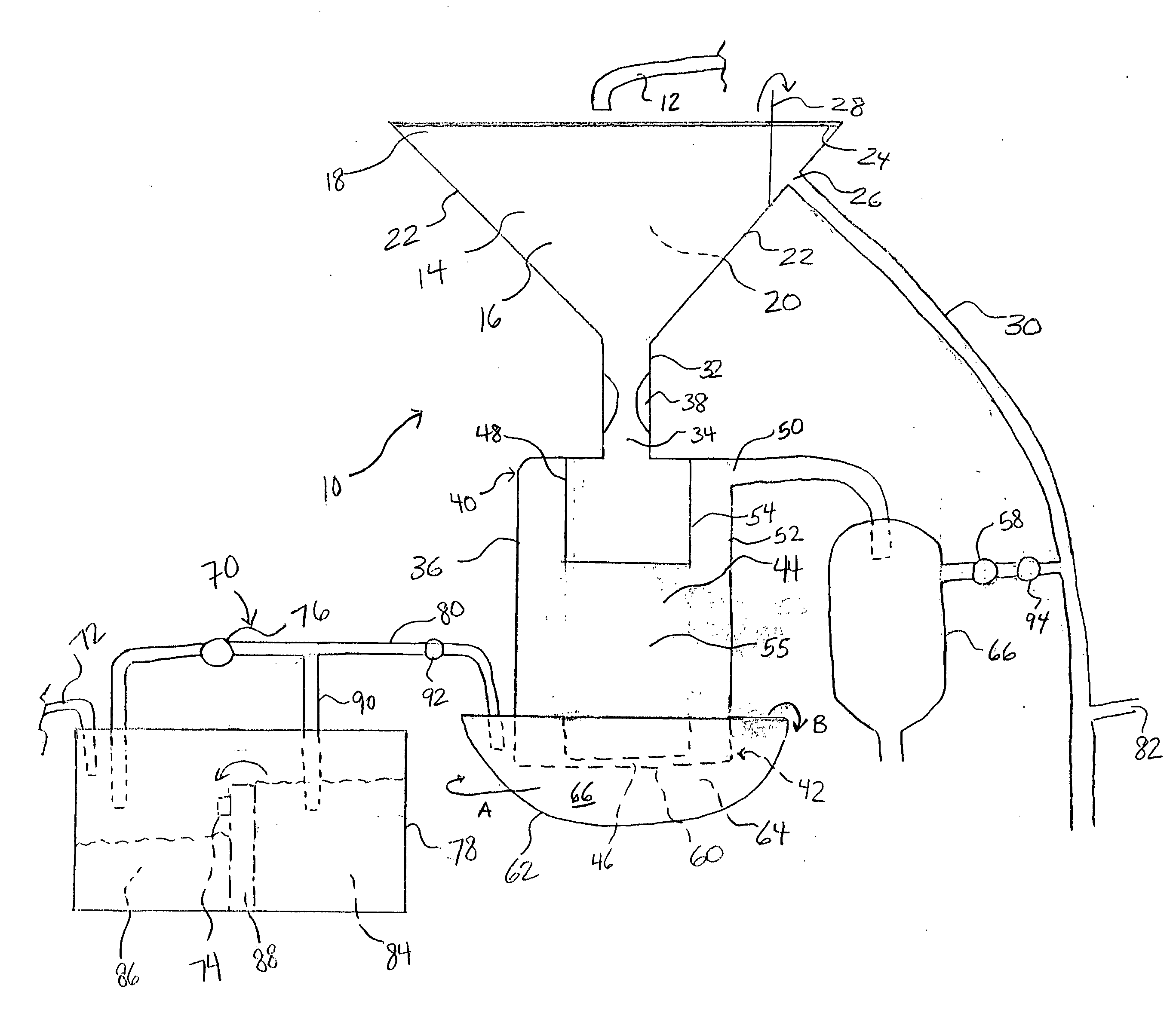
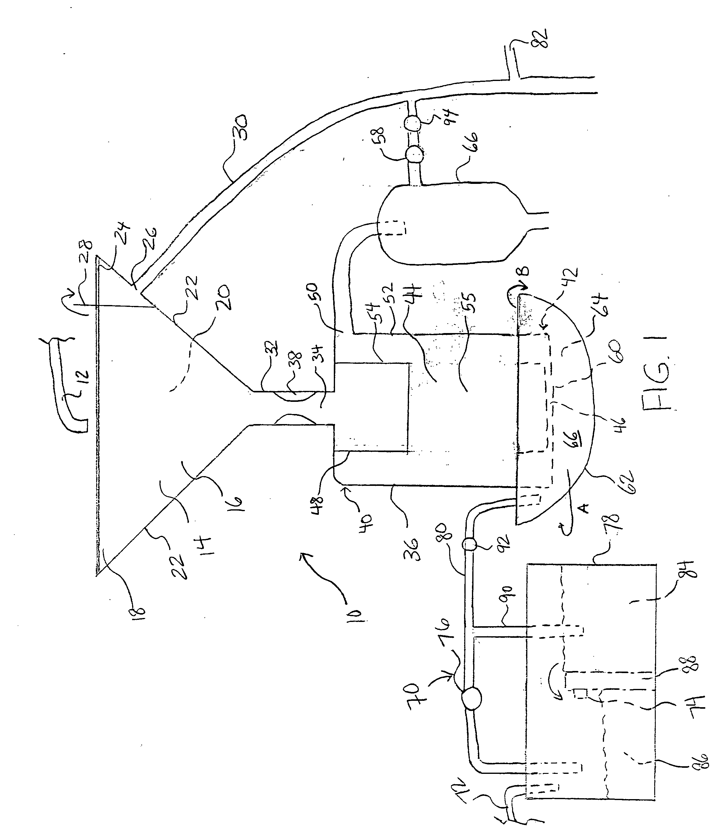
[0053] Referring now to the drawings, FIG. 1 illustrates one embodiment of the system for separating particulate matter based on the particle size and / or density of the particulate matter in accordance with the present invention. Though FIG. 1 depicts a system for separating drill cuttings produced by well digging, tunneling, and horizontal drilling from drill mud and further separating the drill cuttings based on particle size and / or density of the solids, the material to be separated by the method and system of the present invention may also include, but is not limited, to any other matter having at least two solids of a different particle size and / or density. In another embodiment, the present invention may be utilized to separate cement from sand and gravel. In yet another embodiment, the present invention may be utilized to remove fine clay particles from other particulate matter. In yet another embodiment, the present invention may be utilized to separate minerals having diffe...


PUM


Abstract

The present invention is directed to a system and method for continuously or substantially continuously separating particulate matter based on particle size and/or density of the matter. The system includes a separation chamber having a bottom portion disposed within a cavity of a rotatable bowl having fluid therein, preferably water. The internal cavity of the separation chamber is maintained under negative pressure such that fluid is drawn through the separation chamber at a predetermined velocity to separate the solids. Larger, dewatered and/or denser solids are directed to the cavity of the rotatable bowl and can be removed by rotation of the bowl while the smaller and/or less dense solids and fluid travel up through the separation chamber.

Description

CROSS-REFERENCE TO RELATED APPLICATIONS [0001] The present invention claims priority from U.S. Provisional Application Ser. No. 60 / 620,941, filed Oct. 19, 2004.FIELD OF THE INVENTION [0002] The present invention relates to a method and system for separating particulate matter, such as drill cuttings produced by well digging, tunneling, and horizontal drilling, based on particle size and / or density of the matter. BACKGROUND OF THE INVENTION [0003] In rotary drilling operations, a fluid commonly called “drilling mud” is circulated into and out of the hole being drilled. Drilling mud is used to control subsurface pressures, lubricate the drill bit, stabilize the well bore, and carry the cuttings to the surface, among other functions. In a typical drilling mud circulation system, drilling mud is circulated down a drill string, i.e. a pipe and tool configuration, directed through openings in a drill bit on the lower end of the drill pipe, and returned to the surface through the annular s...

Claims


Application Information

Patent Timeline
IPC IPC(8): B03B7/00B07B13/05B07C5/12
CPCB03B5/32B03B7/00B09C1/02E21B21/065Y10S209/915
Inventor WEGNER, PAUL C.
Owner WEGNER PAUL C
Why Eureka
Try Eureka