Pipe gasket with selective economy of scale

Active Publication Date: 2006-04-20
S &B TECHN PROD
View PDF13 Cites 9 Cited by
  • Summary
  • Abstract
  • Description
  • Claims
  • Application Information

AI Technical Summary

Benefits of technology

[0012] One object of the present invention is to provide a sealing gasket for use in a Rieber type manufacturing operation which gasket has a lower overall profile on the mandrel and which utilizes less mass of rubber in the seal

Problems solved by technology

Each of these solutions was less than ideal, in some cases failing to provide the needed joint integrity and often contributing to the complexity and expense of the manuf

Method used


Image

  • Pipe gasket with selective economy of scale
  • Pipe gasket with selective economy of scale
  • Pipe gasket with selective economy of scale

Examples


Example

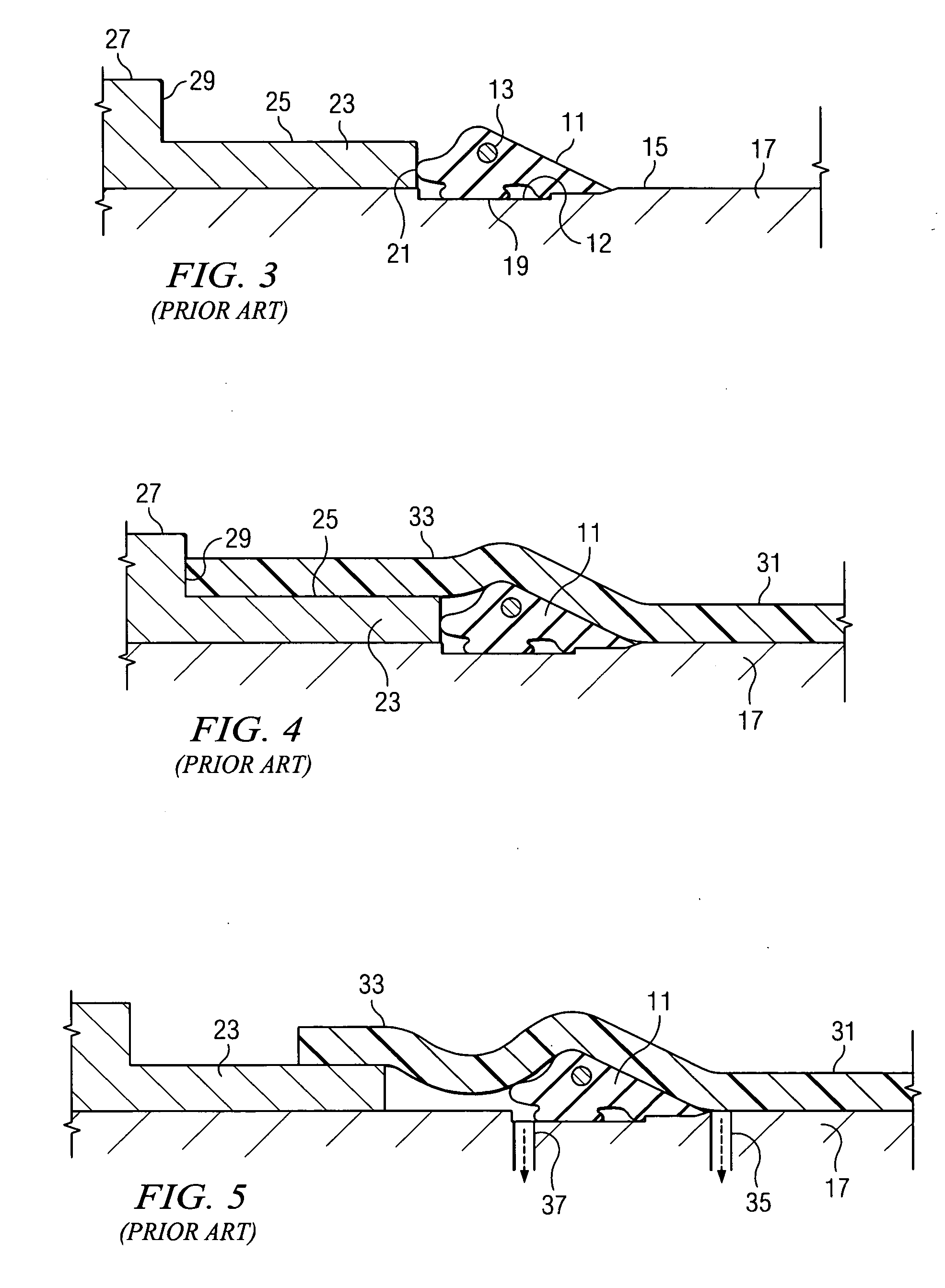
[0027] A first aspect of the present invention concerns the fact that the preferred sealing gaskets in question are “pre-located” within an internal groove provided in the female “belled” pipe end during the manufacture of the pipe in a “Rieber” style manufacturing process. The prior art Rieber process can best be understood with reference to the simplified illustrations provided as FIGS. 3-6 of the drawings.

[0028]FIG. 3 shows an elastomeric sealing gasket 11 having a steel reinforcing ring 13 in place on the generally cylindrical outer working surface 15 of a cylindrically-shaped forming mandrel 17 used in the belling process. Note that in the prior art process, the gasket 11 sits within a slight external groove 12 formed on the exterior of the forming mandrel 17. The elastomeric gasket 11 can be formed of, for example, rubber and is a ring shaped, circumferential member having a lower compression region 19 and an exposed nose portion 21 which, as shown in FIG. 1, abuts a back-up ...


PUM


Abstract

A pipe sealing gasket is shown which is designed to be received within a groove provided within a socket end of a thermoplastic pipe in a pipe sealing system. The sealing system includes a male, spigot pipe end which is joined to a mating female belled pipe end. The belled pipe end has an internal groove adjacent a mouth region thereof which is simultaneously formed under temperature and pressure as the mouth region is forced over a forming mandrel and about a sealing gasket located on the forming mandrel so that the sealing gasket is prelocated within the internal groove. The sealing gaskets of the invention have a sealing capability to seal volume ratio which is numerically related to the same sealing capability to seal volume ratio of prior art gasket designs by a multiplying factor of 2:1 or more.

Description

CROSS-REFERENCE TO RELATED APPLICATIONS [0001] The present application claims priority from earlier filed provisional application Ser. No. 60 / 607,617, filed Sep. 7, 2004, entitled “Pipe Gasket With Selective Economy of Scale,” by Bradford G. Corbett, Jr.BACKGROUND OF THE INVENTION [0002] 1. Field of the Invention [0003] The present invention relates generally to sealing gaskets and sealing systems used for pipe joints in plastic pipelines in which a male spigot pipe section is installed within a mating female socket pipe section to form a pipe joint, and to efforts to economize sealing systems for water, sewer agricultural and other fluid pipe sealing systems employing such pipe joints while maintaining acceptable pressure ratings. [0004] 2. Description of the Prior Art [0005] Fluid sealing systems for plastic, fluid conveying pipes are used in a variety of industries. The pipes used in such systems are typically formed from thermoplastic materials including polyolefins and PVC. In ...

Claims


Application Information

Patent Timeline
IPC IPC(8): F16L37/00
CPCF16L21/03Y10S285/91
Inventor CORBETT, BRADFORD G. JR.DARCE, GERARDOQUESADA, GUIDO
Owner S &B TECHN PROD
Why Eureka
Try Eureka