Electrical connection arrangement having PCB with contacts received therein

Inactive Publication Date: 2011-02-10
HON HAI PRECISION IND CO LTD
View PDF8 Cites 5 Cited by
  • Summary
  • Abstract
  • Description
  • Claims
  • Application Information

AI Technical Summary

Benefits of technology

[0007]Accordingly, an object of the present invention is to provide an improved electrical connection arrangement having a lower profile and a low cost.

Problems solved by technology

However, the housing of socket connector is designed to have a predetermined height and occupies a certain space above the PCB, which thus fails to meet the trend of frivolity in product design.
In another aspect, the housing is made by process of injection molding, and has a relatively high cost.

Method used


Image

  • Electrical connection arrangement having PCB with contacts received therein
  • Electrical connection arrangement having PCB with contacts received therein
  • Electrical connection arrangement having PCB with contacts received therein

Examples


Embodiment Construction

[0017]Reference will now be made to the drawings to describe the present invention in detail.

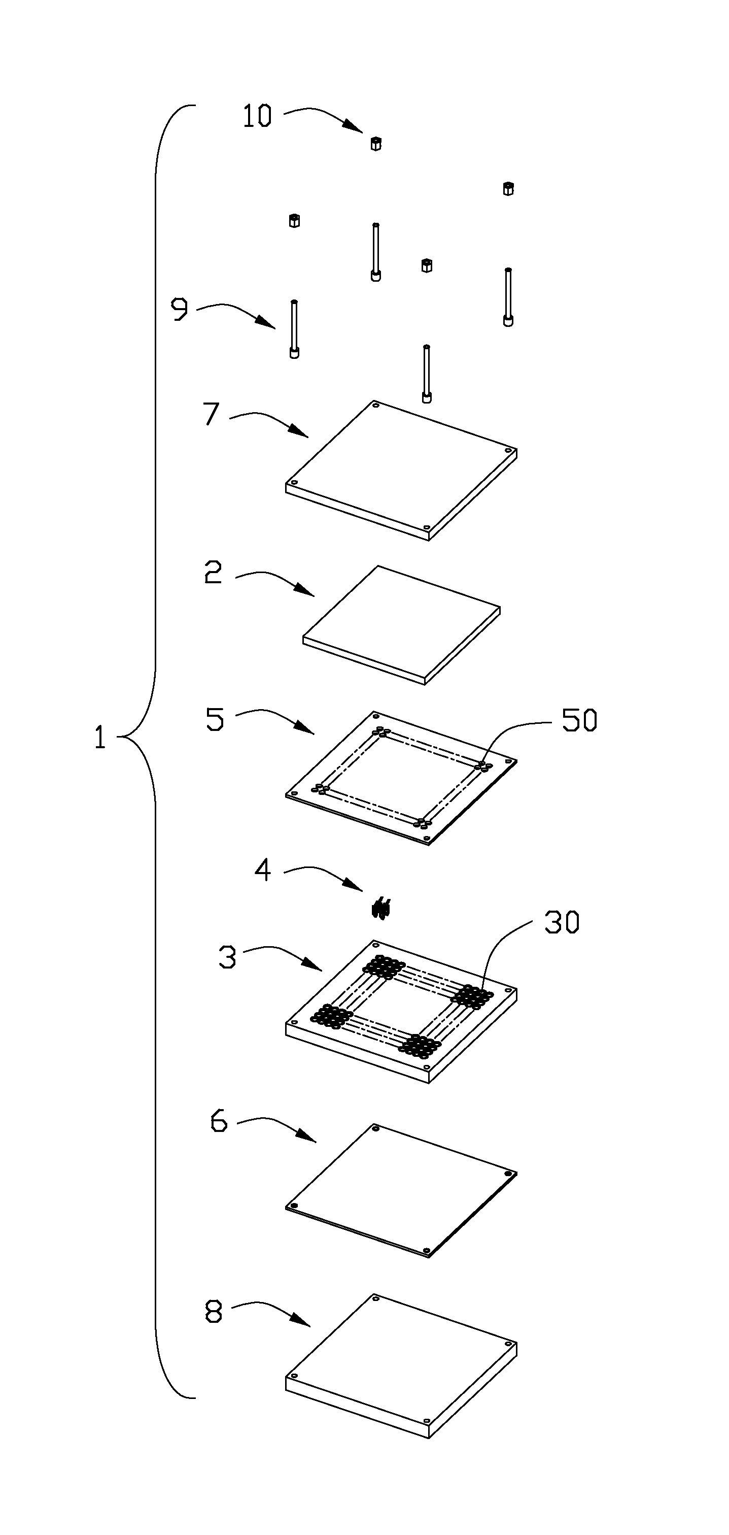
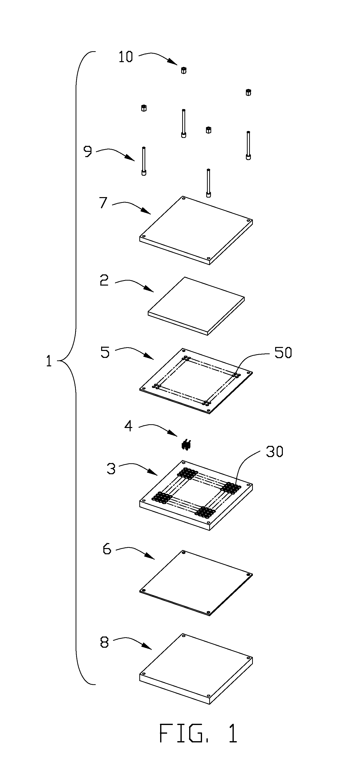
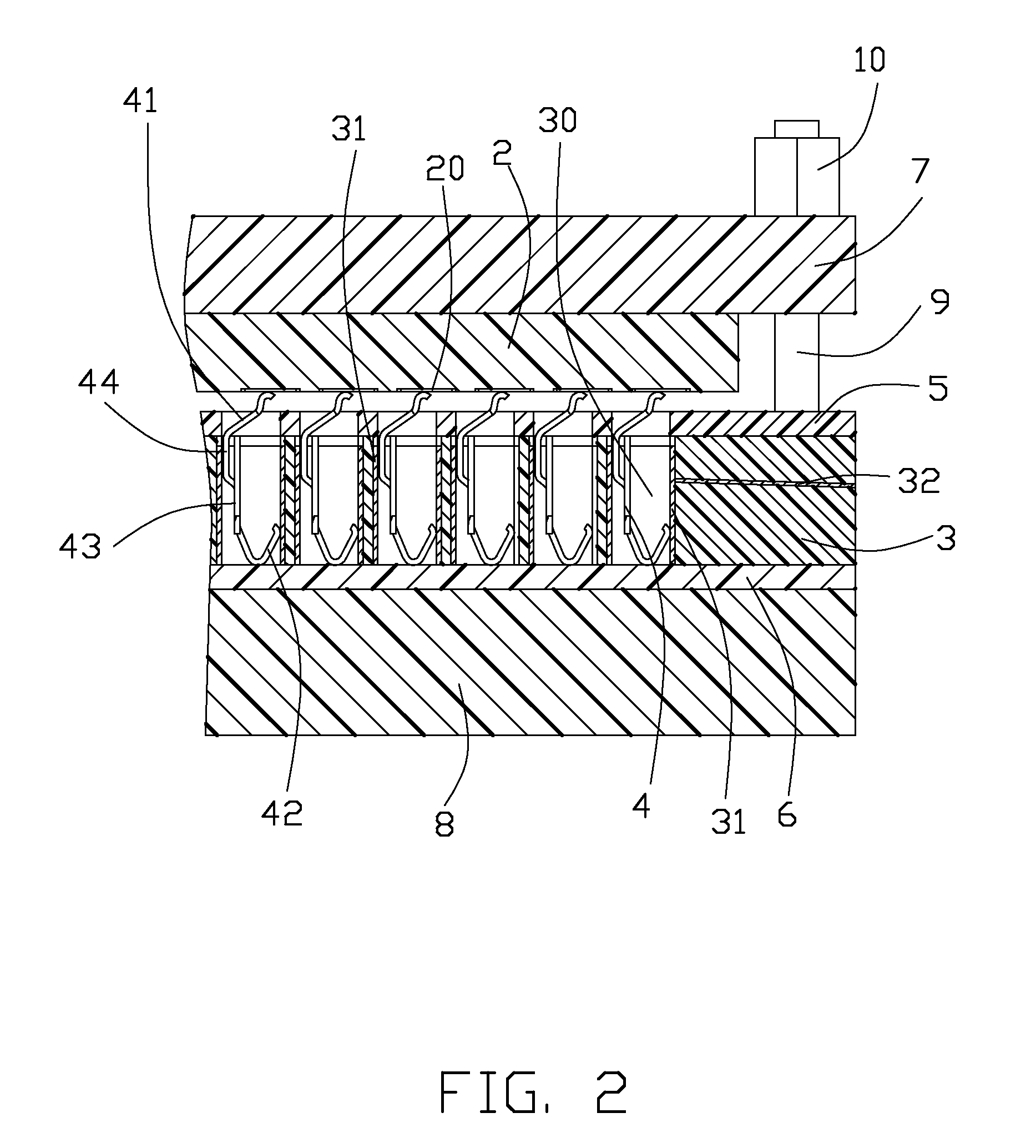
[0018]Referring to FIG. 1 and FIG. 2, an electrical connection arrangement 1 made in accordance with a first preferred embodiment of the present invention for connecting an IC package 2, includes a PCB 3 and a plurality of contacts 4 mounted within in the PCB 3. The PCB 3 has a plurality of receiving holes 30 extending therethrough for receiving the contacts 4 respectively. Each receiving hole 30 has an inner surface provided with a conductive layer 31 thereon which is connected to a circuit trace 32 integrated within the PCB 3. The contact 4 is engaged with and electrically connected to the conductive layer 31.

[0019]Particularly referring to FIG. 2 and FIG. 3, the contacts 4 include grounding contacts and signal contacts (not respectively labeled) which have substantially same structure. Each contact 4 includes a base portion 40, a contacting portion 41 extending upwardly from the base port...


PUM


Abstract

An electrical connection arrangement includes an IC package, and a PCB having a plurality of receiving holes for receiving a plurality of contacts therein. The contact having a contacting portion engaged with the IC package that seated upon the PCB. A retaining device is provided for securing the IC package onto the PCB. Since there is no socket utilized in the present invention, the total profile of the arrangement and the cost are effectively reduced.

Description

BACKGROUND OF THE INVENTION[0001]1. Field of the Invention[0002]The present invention relates to an electrical connection arrangement, and more particularly, to an electrical connection arrangement used for connecting an integrated circuit (IC) package and having a printed circuit board (PCB) with a plurality of contacts received therein.[0003]2. Description of Related Art[0004]A typical socket connector mounted on a PCB for connecting an IC package, typically includes an insulative housing and an array of contacts received in the housing. One end of the contact is connected to the IC package and the other end is engaged with the PCB, such that the electrical connection between the IC package and the PCB is established.[0005]However, the housing of socket connector is designed to have a predetermined height and occupies a certain space above the PCB, which thus fails to meet the trend of frivolity in product design. In another aspect, the housing is made by process of injection mold...

Claims


Application Information

Patent Timeline
IPC IPC(8): H05K7/00H05K1/11
CPCH05K3/308H05K7/1069H05K2201/10393H01R12/7082H05K2201/10704H01R12/714H05K2201/1059
Inventor CHANG, YEN-CHIHCHEN, KE-HAO
Owner HON HAI PRECISION IND CO LTD
Why Eureka
Try Eureka