Material microwave parameter accurate test system introducing machine vision technology and material microwave parameter accurate test method thereof

A microwave parameter and machine vision technology, used in instruments, measuring devices, permeability measurement, etc., can solve the problems of poor test flexibility, increased sample waste, poor test consistency and repeatability, etc., to reduce test inaccuracy, The effect of improving test accuracy and reducing processing time

Inactive Publication Date: 2017-08-22
UNIV OF ELECTRONICS SCI & TECH OF CHINA
View PDF4 Cites 2 Cited by
  • Summary
  • Abstract
  • Description
  • Claims
  • Application Information

AI Technical Summary

Problems solved by technology

In the material microwave parameter testing system, the sample usually needs to be placed in the test fixture, resulting in the shape change of the sample to be tested, which cannot be accurately observed by the naked eye. Even if the free space method is used to test, the sample shape and position change cannot be accurately calculated.
Especially when the size of the sample is inconsistent with the test fixture, it is difficult for the sample to be placed vertically in the fixture, and the inclination of the sample will bring additional errors to the test, and the different states of each sample have different effects on the test results, eventually leading to test Poor consistency and repeatability
[0003] In the traditional microwave material testing method, in order to eliminate the error caused by the change of sample position and shape, the test results are usually corrected by using empirical coefficients or standard samples, but the consistency of test results for different samples is not good, and the theoretical basis is lacking
At the same time, in order to reduce the test error caused by the inclination of the sample, on the one hand, the cross-section of the sample to be tested and the flatness of the fixture surface are improved; The size of the sample requires different fixtures, the test effect is not good, and the test flexibility is poor

Method used


Image

  • Material microwave parameter accurate test system introducing machine vision technology and material microwave parameter accurate test method thereof
  • Material microwave parameter accurate test system introducing machine vision technology and material microwave parameter accurate test method thereof

Examples


Embodiment Construction

[0032] Embodiments of the present invention are described below through specific examples, and those skilled in the art can easily understand other advantages and effects of the present invention from the content disclosed in this specification. The present invention can also be implemented or applied through other different specific implementation modes, and various modifications or changes can be made to the details in this specification based on different viewpoints and applications without departing from the spirit of the present invention.

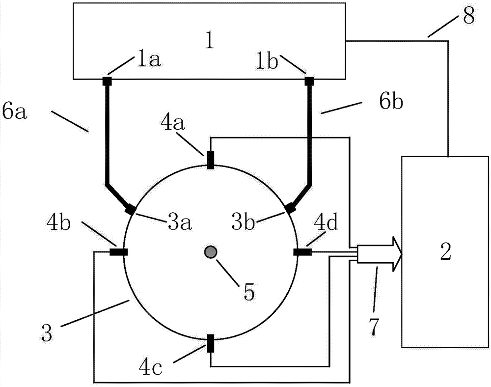
[0033] A material microwave parameter accurate testing system that introduces machine vision technology, including an image acquisition and processing subsystem and a material microwave parameter testing subsystem;

[0034] The image acquisition and processing subsystem includes a computer 2, a plurality of micro-cameras 4a-4d, each micro-camera is connected to the computer 2 through a data transmission line 7, and the plurality of mic...


PUM


Abstract

The invention provides a material microwave parameter accurate test system introducing the machine vision technology. The system comprises an image acquisition and processing subsystem and a material microwave parameter test subsystem. The material microwave parameter accurate test method comprises the steps that firstly each micro-camera is calibrated, rotation matrixes and displacement vectors between each coordinate system and a customized global coordinate system are solved, sample image data are acquired through multiple cameras, the sample three-dimensional coordinates and the real position coordinates and the shape change quantity of the sample material in a test clamp are calculated by using the rotation matrixes and the displacement vectors between each coordinate system and the global coordinate system and the function coefficient or the solution domain in the algorithm is tested to be corrected so as to enhance the test accuracy. The sample position and the shape change can be accurately acquired in real time without influencing microwave material testing so that the influence of the sample position deviation and the shape change on the test result can be effectively reduced and the test accuracy can be further enhanced.

Description

technical field [0001] The invention belongs to the technical field of microwave and millimeter wave material electromagnetic parameter testing, and in particular relates to machine vision technology, a material microwave parameter accurate testing system and a testing method. Background technique [0002] Microwave materials are widely used in various fields such as microwave communication, radar stealth, microwave circuit, remote control and telemetry as the transmission coal of microwave. To use various microwave materials correctly, it is very important to know their dielectric constant accurately. The microwave parameters of materials are generally obtained through testing. Only accurate test results can evaluate the real performance of materials and provide effective reference data for system design and material preparation. In the material microwave parameter testing system, the sample usually needs to be placed in the test fixture, resulting in the shape change of t...

Claims


Application Information

Patent Timeline
Patent Type & Authority Applications(China)
IPC IPC(8): G01R27/26G01R27/02G01R33/12
CPCG01R27/2623G01R27/02G01R33/1223
Inventor 高冲李恩余承勇张云鹏王帅张俊武何凤梅
Owner UNIV OF ELECTRONICS SCI & TECH OF CHINA
Why Eureka
Try Eureka