
Ink-droplet ejecting apparatus

Active Publication Date: 2006-04-20
BROTHER KOGYO KK
View PDF6 Cites 11 Cited by
  • Summary
  • Abstract
  • Description
  • Claims
  • Application Information

AI Technical Summary

Benefits of technology

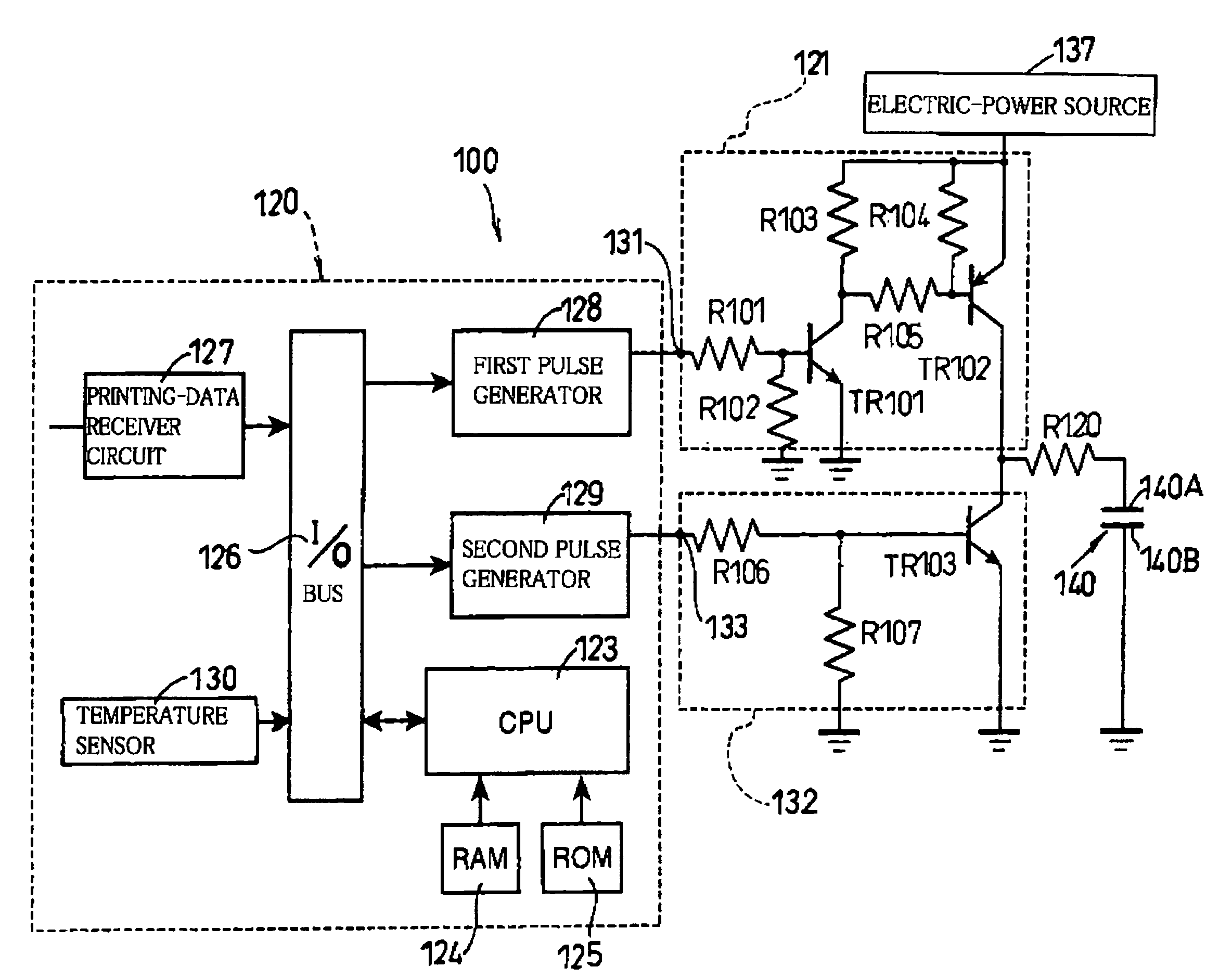
[0015] It is therefore an object of the present invention to solve at least one of the above-indicated problems. It is another object of the present invention to provide an ink-droplet ejecting apparatus that can record an image with a stable quality by using ejection pulse signals and cancel pulse signals respective pulse lengths of which and a pulse interval between two pulse signals of which are determined based on a one-way propagation time of a pressure wave.

Problems solved by technology

However, recently, inkjet image recording devices have been required to record images at higher speeds.

Method used


Image

  • Ink-droplet ejecting apparatus
  • Ink-droplet ejecting apparatus
  • Ink-droplet ejecting apparatus

Examples


experiment 1

[0071] Experiment 1—FIG. 7A

[0072] In this experiment, respective pulse lengths WF of the first and second ejection pulses PF1, PF2 are equal to 1.0AL (this is true with all experiments 1 through 6). Respective pulse lengths of the first and second cancel pulses PS1, PS2 are equal to from 1.3AL to 1.8AL. A time interval between the rise SE1 of the first cancel pulse PS1 and the fail FS2 of the second ejection pulse PF2 is equal to from 3.0AL to 4.5AL. The results of this experiment show that when the duty percentage is equal to 50.0% or 25.0%, the ink ejections are bad (“X”) with respect to the entire frequency range of from 18 kHz to 26.4 kHz; when the duty percentage is equal to 12.5%, the ink ejections are good (“O”) with respect to the entire frequency range; and when the duty percentage is equal to 33.0%, the ink ejections are deflected (“Δ”) with respect to a frequency range of from 25.2 kHz to 26.4 kHz.

experiment 2

[0073] Experiment 2—FIG. 7B In this experiment, respective pulse lengths of the first and second cancel pulses PS1, PS2 are equal to from 0.3AL to 0.4AL. A pulse interval between the rise SE1 of the first cancel pulse PS1 and the fall FS2 of the second ejection pulse PF2 is equal to from 3.0AL to 4.5AL. The results of this experiment show that when the duty percentage is equal to 12.5%, the ink ejections are good (“O”) with respect to the entire frequency range; when the duty percentage is equal to 50.0% or 33.0%, the ink ejections are bad (“X”) with respect to the entire frequency range; and when the duty percentage is equal to 25.0%, the ink ejections are deflected (“Δ”) with respect to a frequency range of from 24.0 kHz to 26.4 kHz.

experiment 3

[0074] Experiment 3—FIG. 7C

[0075] In this experiment, a pulse length of the first cancel pulse PS1 is equal to from 0.3AL to 0.4AL and a pulse length of the second cancel pulse PS2 is equal to from 1.3AL to 1.8AL. A pulse interval between the rise SE1 of the first cancel pulse PS1 and the fall FS2 of the second ejection pulse PF2 is equal to from 3.0AL to 4.5AL. The results of this experiment show that when the duty percentage is equal to 12.5%, the ink ejections are good (“O”) with respect to the entire frequency range; when the duty percentage is equal to 50.0%, the ink ejections are deflected (“Δ”) with respect to a wide frequency range of from 21 kHz: to 26.4 kHz; and when the duty percentage is equal to 33.0%, the ink ejections are deflected or bad (“X”) with respect to a wide frequency range of from 21 kHz to 26.4 kHz. In addition, when the duty percentage is equal to 25.0%, the ink ejections are bad with respect to a frequency range of from 18 kHz to 20 kHz.


PUM


Abstract

An ink-droplet ejecting apparatus including a nozzle; a pressure chamber ailed with ink; an actuator which produces a pressure wave in the ink; and a control device which, when a first print command corresponding to a first print period is to eject the ink and a second print command corresponding to a second print period next to the first print period is to eject the ink, outputs, within the first print period, a first drive waveform so as to drive, a plurality of times, the actuator, and which, when the first print command is to eject the ink and the second print command is not to eject the ink, outputs a second drive waveform extending over the first and second print periods. The control device outputs, as the second drive waveform, a first ejecting pulse signal, then a first canceling pulse signal, then a second ejecting pulse signal and then a second canceling pulse signal, so as to drive, two times, the actuator. Each of the first and second ejecting pulse signals has a pulse length falling in a range of from 0.8AL to 1.2AL, where AL is a one-way propagation time needed for the pressure wave to propagate one way in an ink flow passage which includes the pressure chamber and is connected to the nozzle. The first canceling pulse signal has a pulse length falling in a range of from 1.3AL to 1.8AL, and the second canceling pulse signal has a pulse length falling in a range of from 0.3AL to 0.4AL. A time interval between a trailing end of the first canceling pulse signal and a leading end of the second ejecting pulse signal fall in a range of from 3.0AL to 4.5AL.

Description

[0001] The present application is based on Japanese Patent Application No. 2004-300456 filed on Oct. 14, 2004, the contents of which are incorporated herein by reference. BACKGROUND OF THE INVENTION [0002] 1. Field of the Invention [0003] The present invention relates to an ink-droplet ejecting apparatus of an inkjet type that drives an actuator to produce a pressure wave or vibration in a pressure chamber and thereby eject a droplet of ink from a nozzle. [0004] 2. Discussion of Related Art [0005] There has been known an ink-droplet ejecting device including an ink ejection nozzle, a pressure chamber (i.e., an ink chamber) that is provided in rear of the nozzle and is filled with ink, an actuator that changes a volume of the pressure chamber, and a control device that drives the actuator to produce a pressure wave or vibration in the pressure chamber and thereby eject a droplet of the ink from the nozzle. [0006] For example, Patent Document 1 (Japanese Patent Application Publication...

Claims


Application Information

Patent Timeline
IPC IPC(8): B41J29/38
CPCB41J2/04581B41J2/04588B41J2/04593B41J2/04596B41J2002/14217B41J2002/14225B41J2002/14306B41J2002/14419
Inventor TAKAHASHI, YOSHIKAZU
Owner BROTHER KOGYO KK
Features
  • Generate Ideas
  • Intellectual Property
  • Life Sciences
  • Materials
  • Tech Scout
  • Unparalleled Data Quality
  • Higher Quality Content
  • 60% Fewer Hallucinations
Learn More