Combination mop wringer and bucket system

Inactive Publication Date: 2006-04-27
QUICKIE MFG
View PDF18 Cites 15 Cited by
  • Summary
  • Abstract
  • Description
  • Claims
  • Application Information

AI Technical Summary

Benefits of technology

[0010] It is a further object of the present invention to provide a combination wringer and mop bucket system which has a minimum number of parts and which is easy to manufacture and assemble.
[0011] These and other objects are accomplished by the combination wringer/bucket system of the present invention. The system uses a wringer consisting of a wringer basket and pressure plate, specifically configured to be mounted on the rim of the bucket, which itself is specially adapted to receive and support a separable, columnar, wringer bas

Problems solved by technology

However, while some of these prior systems are effective in performing the mop wringing function, they are generally unstable, given the top heavy design of the wringer on the bucket.
The very mounting of the wringer on the rim of the bucket results in the wringer being unsteady.
This instability is exacerbated when the mo

Method used


Image

  • Combination mop wringer and bucket system
  • Combination mop wringer and bucket system
  • Combination mop wringer and bucket system

Examples


Embodiment Construction

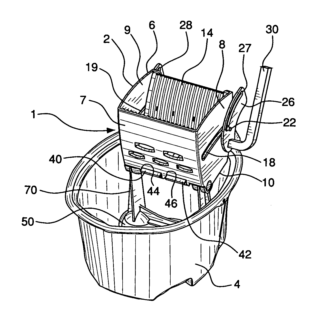
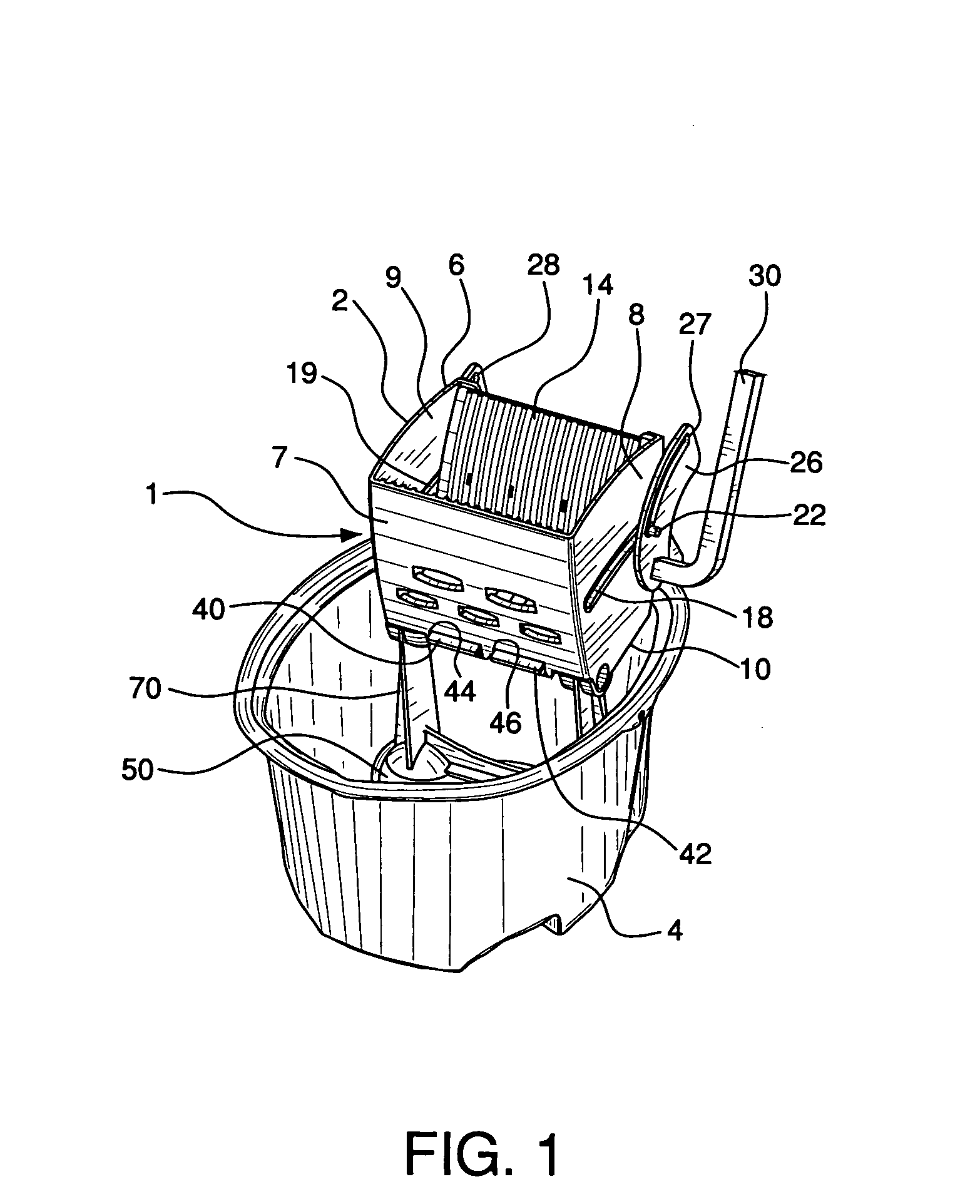
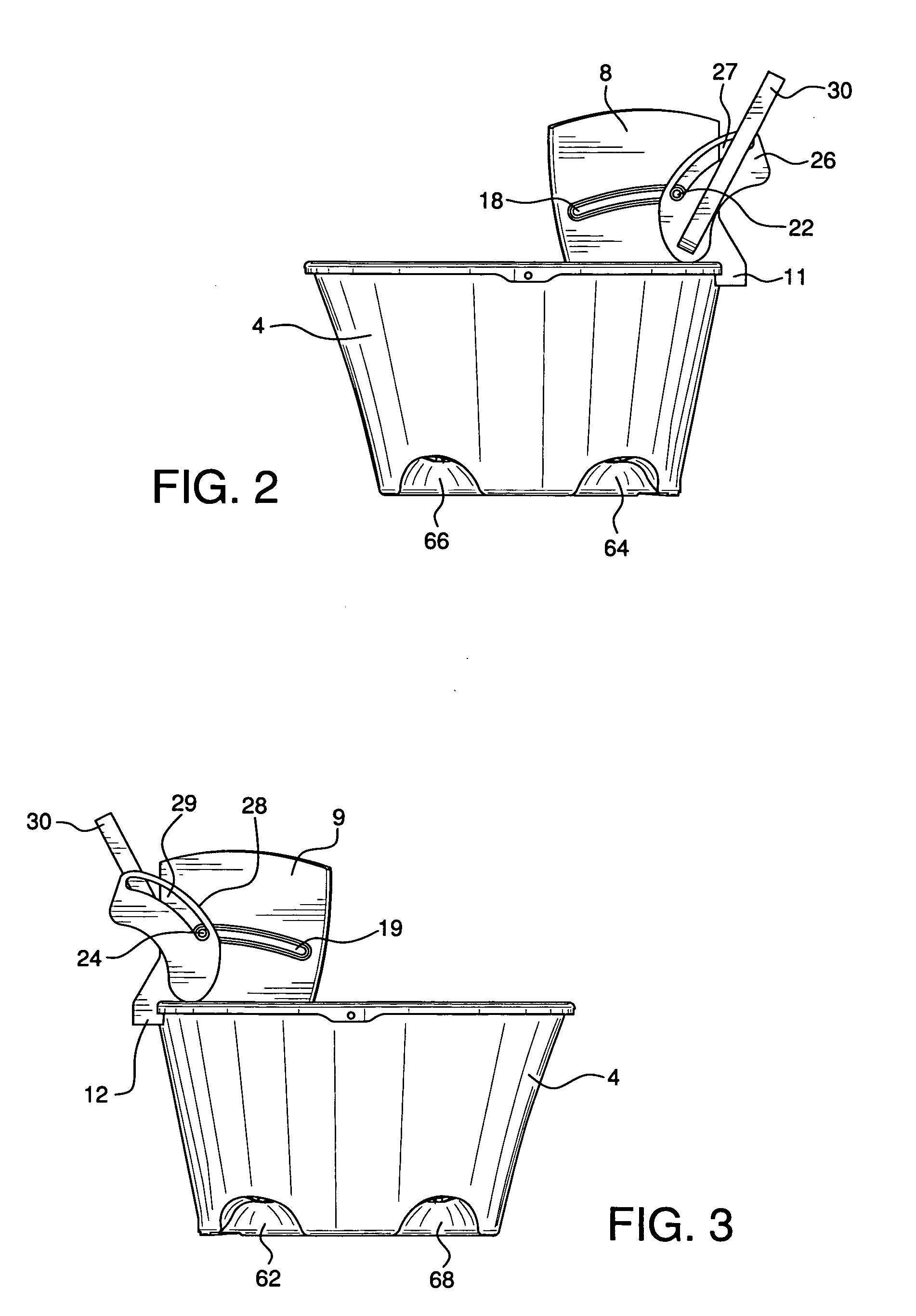
[0027] The wringer / bucket system 1 of the present invention consists of a mop wringer 2 and mop bucket 4. Wringer 2 comprises wringer basket 6 with front surface 7, side surfaces 8 and 9, and bottom surface 10. Basket 6 is substantially open between side surfaces 8 and 9. Pressure plate 14 extends into basket 6 and is mounted within the basket by a cam type system which comprises rod 16 positioned within arcuate slots 18 and 19 located in side surfaces 8 and 9 respectively. Rod 16 is mounted within slots 18 and 19 by means of capped bearings 22 and 24. Rod 16 is positioned adjacent to and extends across the rear surface of pressure plate 14, as seen in FIG. 5, and is configured to be moveable up and down within slots 18 and 19.

[0028] The cam type system also includes dual slotted cam components 26 and 28. Substantially upwardly extending handle 30 is connected to cam component 26. The ends of rod 16 and its bearings 22 and 24 extend through slots 27 and 29 in cam components 26 and ...


PUM


Abstract

A combination wringer/bucket system uses a wringer consisting of a wringer basket and pressure plate, specifically configured to be mounted on the rim of the bucket, which itself is specially adapted to receive and support a separable, columar wringer basket support member. This member extends between the floor of the bucket and the basket and provides stability to the bucket mounted wringer. The support member can be removed from the bucket, as can the wringer, so that the bucket can be used alone, if desired. For providing additional stability to the wringer, leg components extend from the pressure plate, through the wringer basket. A cam operated system smoothly controls the movement of the pressure plate within the wringer, to efficiently and effectively wring out saturated mops.

Description

BACKGROUND OF THE INVENTION [0001] Mop wringer / bucket combination systems are widely used in floor cleaning and swabbing operations, especially in, but not limited to, commercial environments. In normal practice, once the swab type mop employed to clean or mop a floor has become saturated, it is inserted into the wringer, where its moisture is squeezed out of the mop strands and into the bucket which mounts the wringer. The mop is then withdrawn from the wringer for further mopping. This basic system is also commonly used to clean floor surfaces when there is a cleaning liquid in the bucket. The swab mop is inserted into the bucket to soak in the liquid and is then put through the wringer to shed its excess liquid before being used on the floor. [0002] There are many such commonly used wringer / bucket combination systems, some of which are disclosed in U.S. Pat. No. 5,070,574, U.S. Pat. No. 5,440,778, U.S. Pat. No. 5,548,865, U.S. Pat. No. 5,615,446, U.S. Pat. No. 5,974,621, and U.S....

Claims


Application Information

Patent Timeline
IPC IPC(8): A47L13/59
CPCA47L13/59
Inventor PETNER, ROBERT E.
Owner QUICKIE MFG
Why Eureka
Try Eureka