
Apparatus and method for processing an image signal in a digital broadcast receiver

a digital broadcast receiver and image signal technology, applied in the field of apparatus and method for receiving and processing broadcast signals by portable terminals, can solve the problems of limited image size of portable terminals, complicated processes, and complicated structure of portable terminals

Inactive Publication Date: 2006-04-27
SAMSUNG ELECTRONICS CO LTD
View PDF15 Cites 121 Cited by
  • Summary
  • Abstract
  • Description
  • Claims
  • Application Information

AI Technical Summary

Benefits of technology

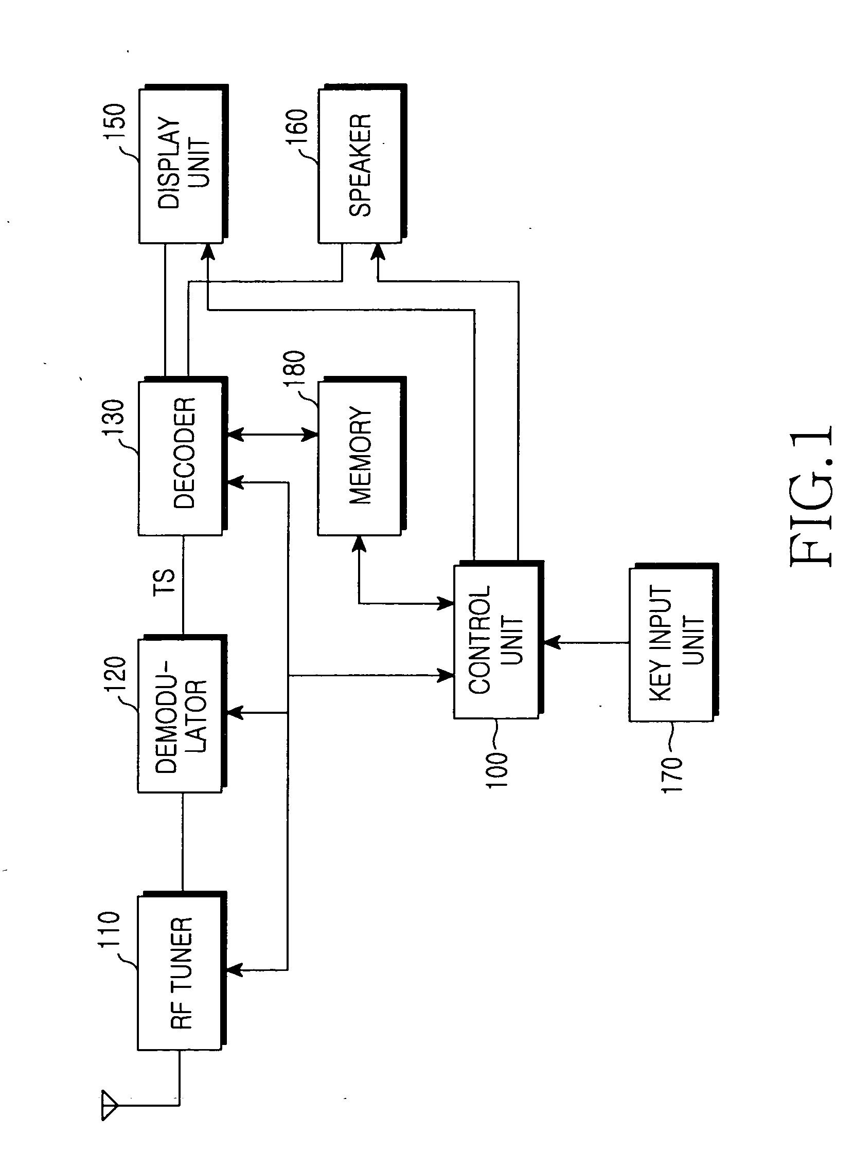
[0011] It is another object of the present invention to provide a decoding apparatus and method, which can process a received broadcast signal according to standards of a portable terminal having a digital broadcast reception function.
[0013] It is another object of the present invention to provide an apparatus and method, which can select an area of a received broadcast image signal and decode the signal according to the scan type of the signal in a portable terminal having a digital broadcast reception function.
[0014] It is another object of the present invention to provide an apparatus and method, which can select an area of a received broadcast image signal and decode the signal according to the scan type of the signal and a display size in a portable terminal having a digital broadcast reception function.

Problems solved by technology

Therefore, it is necessary for the current portable terminals to provide various multimedia functions, which results in the portable terminals having a more complicated structure and having to perform more complicated processes.
For example, the display unit of the portable terminal is small relative to that of a typical image processing unit, so it is limited in the size of the image it can display.

Method used


Image

  • Apparatus and method for processing an image signal in a digital broadcast receiver
  • Apparatus and method for processing an image signal in a digital broadcast receiver
  • Apparatus and method for processing an image signal in a digital broadcast receiver

Examples


Embodiment Construction

[0050] Hereinafter, preferred embodiments of the present invention will be described in detail with reference to the accompanying drawings. In the following description, the same elements will be designated by the same reference numerals although they are shown in different drawings.

[0051] Further, various specific definitions found in the following description, such as communication frequencies of a digital broadcast receiver, data structure, etc., are provided only to help general understanding of the present invention, and it is apparent to those skilled in the art that the present invention can be implemented without such definitions.

[0052] The present invention provides an apparatus and method, which analyze a display size, etc., of a received signal, resize a decoding area of the signal, and then decode data in the resized area. In the apparatus and method according to the present invention, the decoding area is adaptively resized according to the characteristics of the digi...


PUM


Abstract

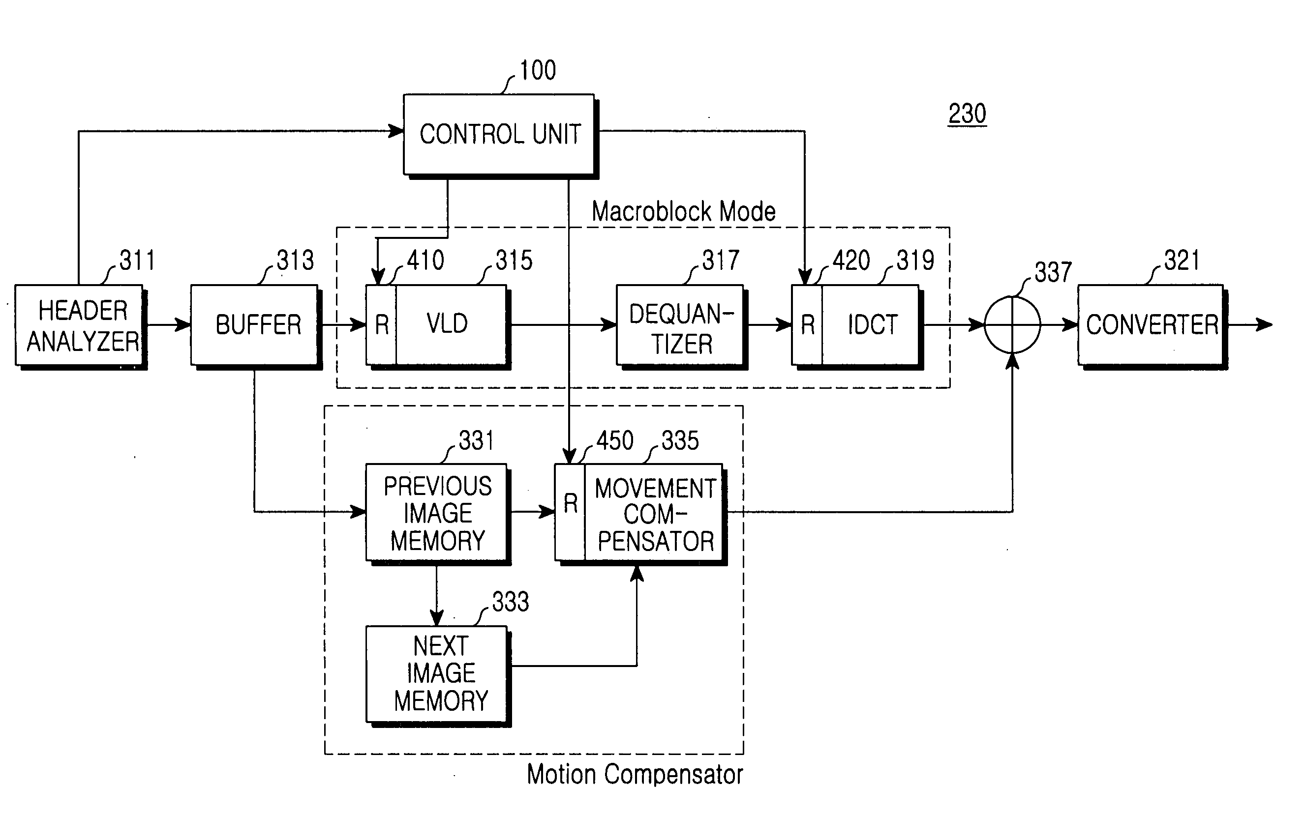
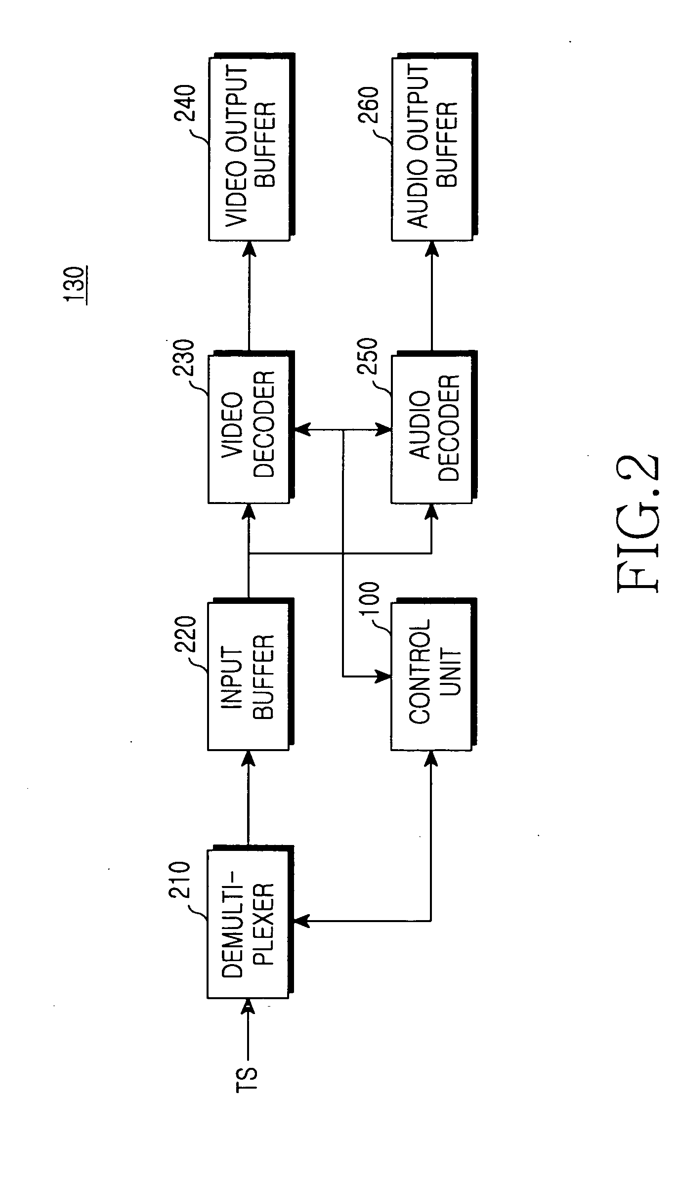
A method and apparatus for decoding a coded video data in a digital broadcast receiver. The method includes: determining a resizing control signal for resizing a received video data; analyzing header information from a decoded video stream and separating and outputting a video data; resizing the separated video data by the resizing control signal and decoding the resized video data into an original pixel data with an original data size by using a variable length table; dequantizing the decoded video data; resizing and converting the dequantized frequency-domain video data into a two dimensional spatial domain video data by the resizing control signal; movement compensating for movement of a movement compensation data corresponding to one of the inverse-transformed video data and the separated video data; and converting outputs of the inverse transform unit and the movement compensation unit into display data for a display unit.

Description

PRIORITY [0001] This application claims priority to an application entitled “Apparatus and Method For Processing Image Signal In Digital Broadcast Receiver” filed in the Korean Industrial Property Office on Oct. 26, 2004 and assigned Serial No. 2004-85860, and to Korean Patent Application Serial No. 100299 / 2005 filed in the Korean Industrial Property Office on Oct. 24, 2005, the contents of which are hereby incorporated by reference. BACKGROUND OF THE INVENTION [0002] 1. Field of the Invention [0003] The present invention relates to an apparatus and method for receiving and processing a broadcast signal by a portable terminal. [0004] 2. Description of the Related Art [0005] Currently, portable terminals are being equipped with a dedicated processor for multimedia or have an enhanced multimedia function. Further, technologies for mounting a television function to the portable terminals are being released and technologies for mounting a digital broadcast receiver are currently being r...

Claims


Application Information

Patent Timeline
Patent Type & Authority Applications(United States)
IPC IPC(8): H04N11/02H04N7/12H04N11/04
CPCH04N21/25808H04N19/1887H04N21/41407H04N21/434H04N21/4402H04N21/440263H04N21/4621H04N19/46H04N19/51H04N19/122H04N19/61H04N19/132H04N19/156H04N19/16H04N19/162H04N19/18H04N19/48H04N19/44H04N19/59H04N21/2662
Inventor SEO, JEONG-WOOKLEE, DONG-YULKIM, HWANPARK, WEI-JIN
Owner SAMSUNG ELECTRONICS CO LTD
Learn More