
Vehicle illumination lamp

Inactive Publication Date: 2006-04-27
KOITO MFG CO LTD
View PDF5 Cites 121 Cited by
  • Summary
  • Abstract
  • Description
  • Claims
  • Application Information

AI Technical Summary

Benefits of technology

[0009] The present invention has been conceived in view of the above circumstances, and aims at providing a vehicle illumination lamp, which employs a light-emitting element as a light source, being capable of forming a light distribution pattern having a sharp cutoff line, in addition to increasing a utilization rate of the light flux in relation to light from the light-emitting element.

Problems solved by technology

However, this configuration of the vehicle illumination lamp involves a problem that a light distribution pattern having a sharp cutoff line cannot be formed from light illuminated from the vehicle illumination lamp.

Method used


Image

  • Vehicle illumination lamp
  • Vehicle illumination lamp
  • Vehicle illumination lamp

Examples


Embodiment Construction

[0027] Although the invention will be described below with reference to the exemplary embodiment and modifications thereof, the following exemplary embodiment and modifications do not restrict the invention.

[0028] As to the term of “translucent” in this invention, it is noted that said term shall be construed rather broadly such as to cover the meaning of “transparent” whose optical characteristic might be included in the definition of “translucent” that is known for a person skilled in the art.

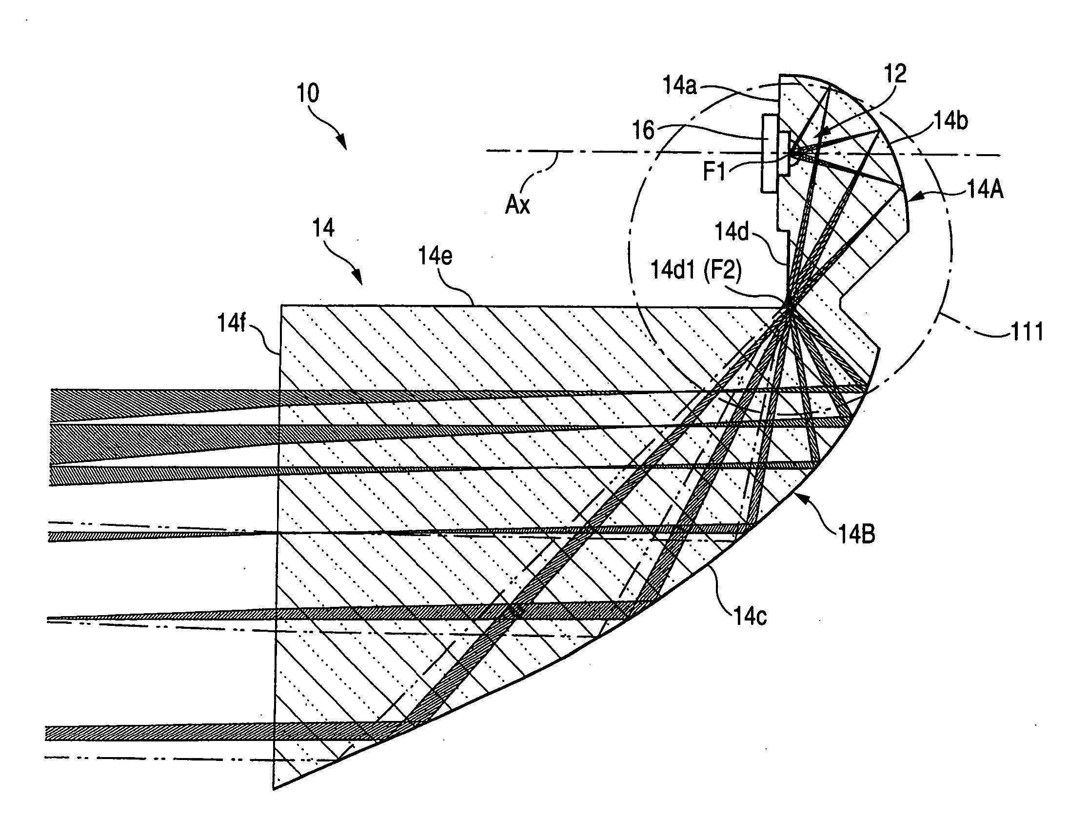
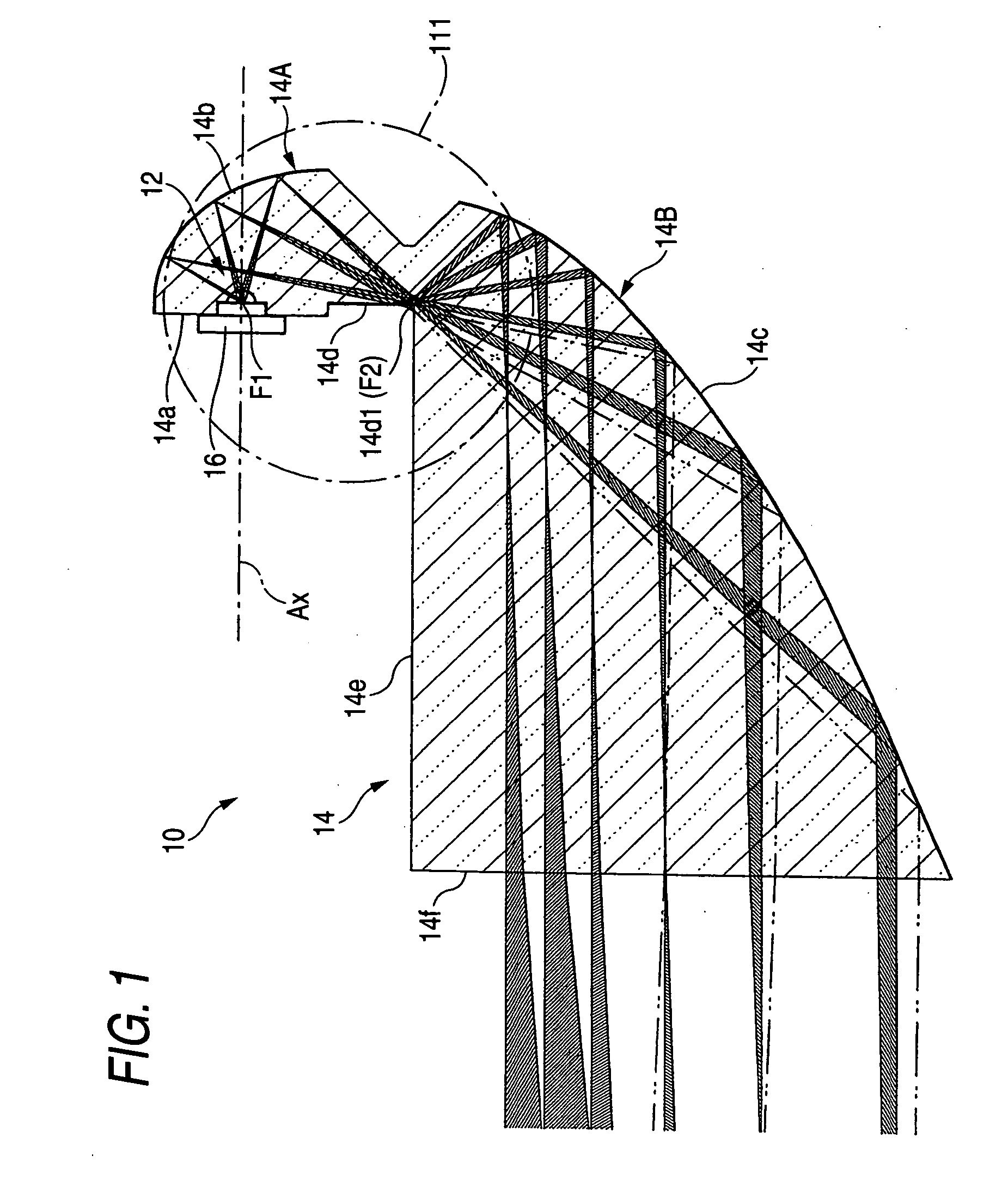
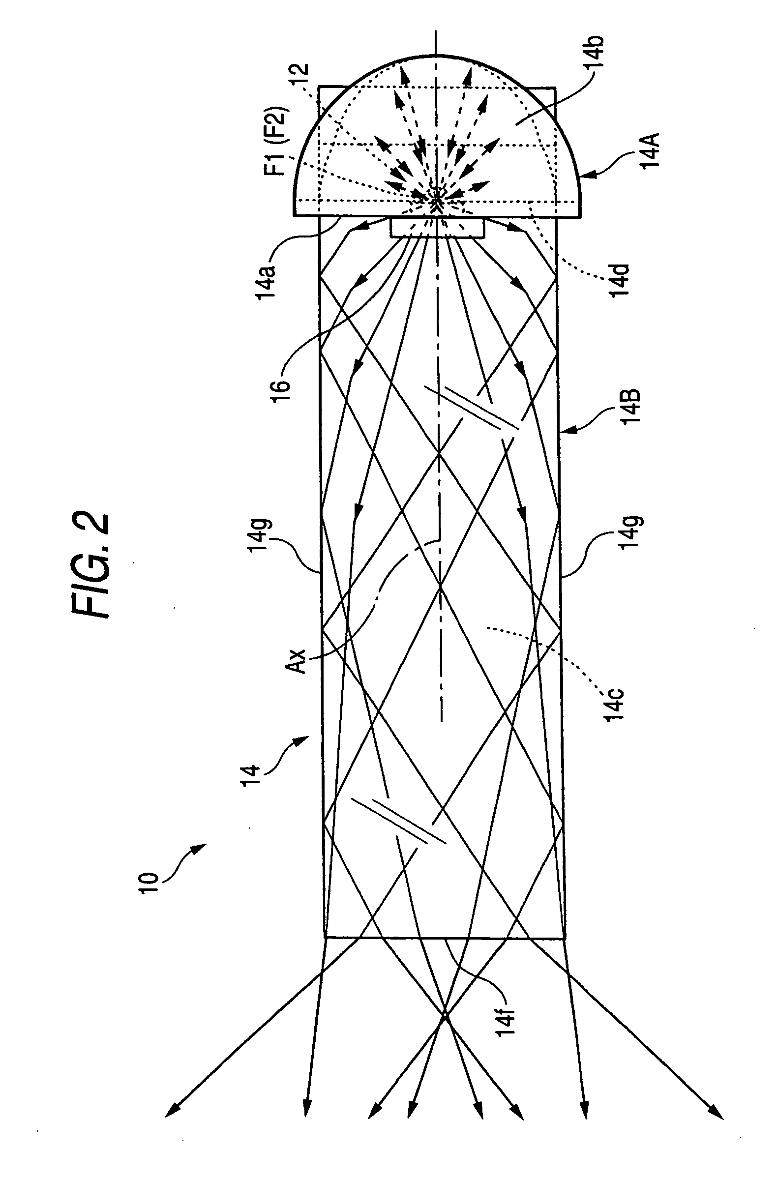
[0029]FIG. 1 is a side cross-sectional view illustrating a vehicle illumination lamp 10 according to an embodiment of the invention, FIG. 2 is a plane view illustrating the same, and FIG. 3 is a detailed view of a portion III of FIG. 1. FIG. 4 is an exploded perspective view illustrating the vehicle illumination lamp 10.

[0030] As illustrated in these drawings, the vehicle illumination lamp 10 is a lamp unit to be used as a portion of a headlamp. The vehicle illumination lamp 10 comprises a...


PUM


Abstract

A vehicle illumination lamp having a light-emitting element including an optical axis, a first reflection surface, a second reflection surface, and a third reflection surface. The third reflecting surface is formed on a plane intersecting the optical axis in such a manner as to include a first focal point and a second focal point of the first reflecting surface.

Description

[0001] This application claims foreign priority from Japanese Patent Application No. 2004-312837, filed Oct. 27, 2004, the entire disclosure of which is herein incorporated by reference. BACKGROUND OF THE INVENTION [0002] 1. Field of the Invention [0003] The present invention relates to a vehicle illumination lamp employing a light-emitting element, such as a light-emitting diode, as a light source. [0004] 2. Description of Related Art [0005] In recent years, an illumination lamp employing a light-emitting element, such as a light-emitting diode, as a light source has been developed as a vehicle illumination lamp, such as a headlamp. [0006] In relation to the above, Japanese Patent Publication 2001-332104 discloses a vehicle illumination lamp having a first reflection surface for reflecting light from a light-emitting element, which is disposed facing a lateral direction of the lamp, rearward in relation to the lamp and a second reflection surface for reflecting in a forward directi...

Claims


Application Information

Patent Timeline
IPC IPC(8): F21V7/00
CPCF21S48/1159F21S48/1163F21S48/1241F21S48/215F21S48/2243F21S48/2262F21S48/2287F21V7/0008F21Y2101/02F21Y2115/10F21S41/147F21S41/285F21S41/24F21S41/321F21S41/322F21S41/323F21S41/43F21S41/365F21S41/145F21S41/155F21S43/247F21S43/243F21S43/239F21S43/14
Inventor ISHIDA, HIROYUKI
Owner KOITO MFG CO LTD
Features
  • Generate Ideas
  • Intellectual Property
  • Life Sciences
  • Materials
  • Tech Scout
  • Unparalleled Data Quality
  • Higher Quality Content
  • 60% Fewer Hallucinations
Learn More