
Engine mounting arrangement for two wheeled vehicle

a two-wheeled vehicle and engine mounting technology, applied in the direction of crankshaft transmission, friction roller based transmission, cycles, etc., can solve the problems of increasing the distance between the crankcase and the main frame member, and it is difficult for a rider to put both feet on the ground easily, so as to achieve ample space and reduce the main frame member

Inactive Publication Date: 2006-05-04
YAMAHA MOTOR CO LTD
View PDF11 Cites 13 Cited by
  • Summary
  • Abstract
  • Description
  • Claims
  • Application Information

AI Technical Summary

Benefits of technology

The present invention provides a motorcycle that allows the main frame member to be lowered while still suspending a power unit and providing ample space for an auxiliary component between the case of the power unit and the main frame member. This allows for a more compact motorcycle design and improved performance.

Problems solved by technology

The upward displacement results in an increase in distance between the crankcase and the main frame member.
The seat, then, is positioned fairly high on the vehicle, which makes it difficult for a rider to put both feet on the ground easily.

Method used


Image

  • Engine mounting arrangement for two wheeled vehicle
  • Engine mounting arrangement for two wheeled vehicle
  • Engine mounting arrangement for two wheeled vehicle

Examples


Embodiment Construction

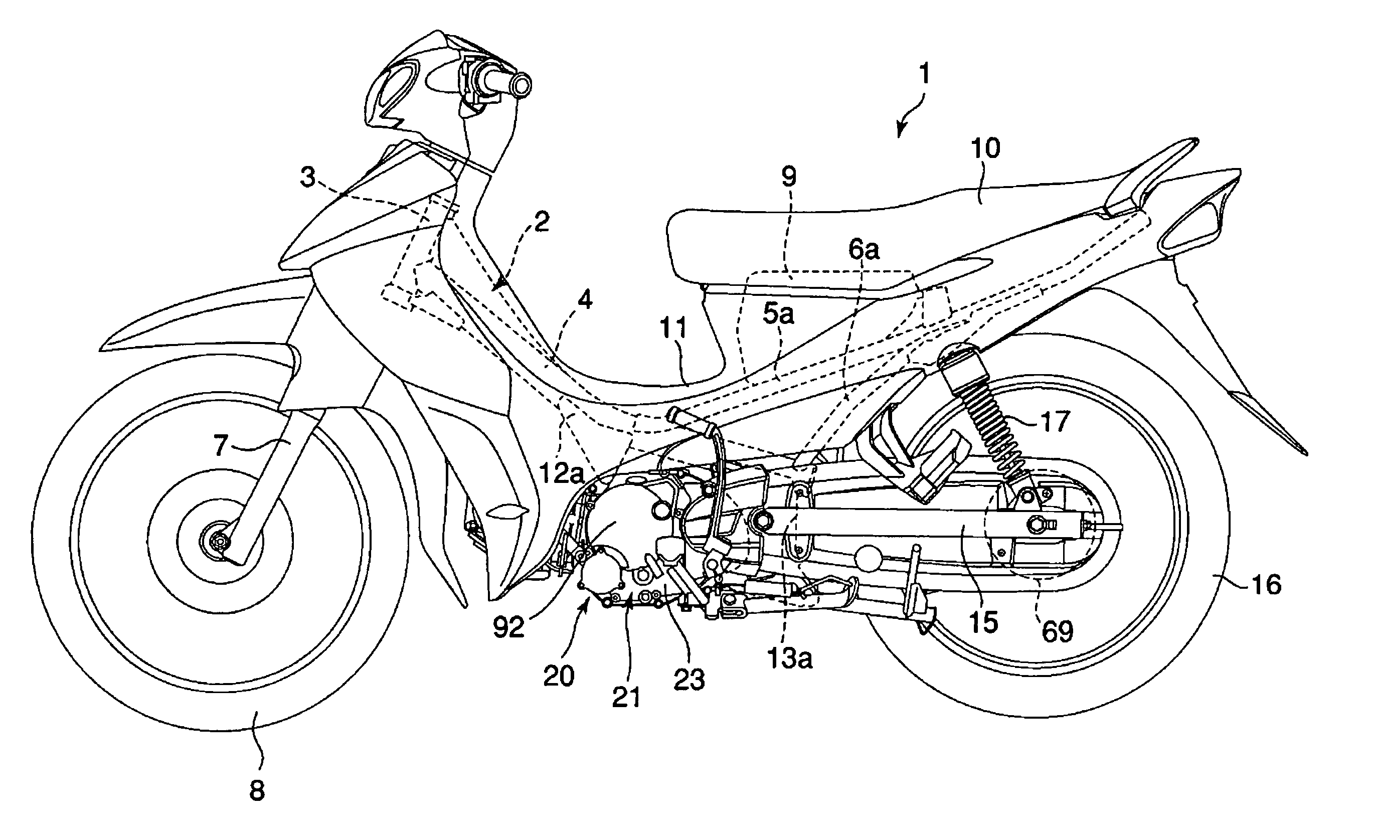
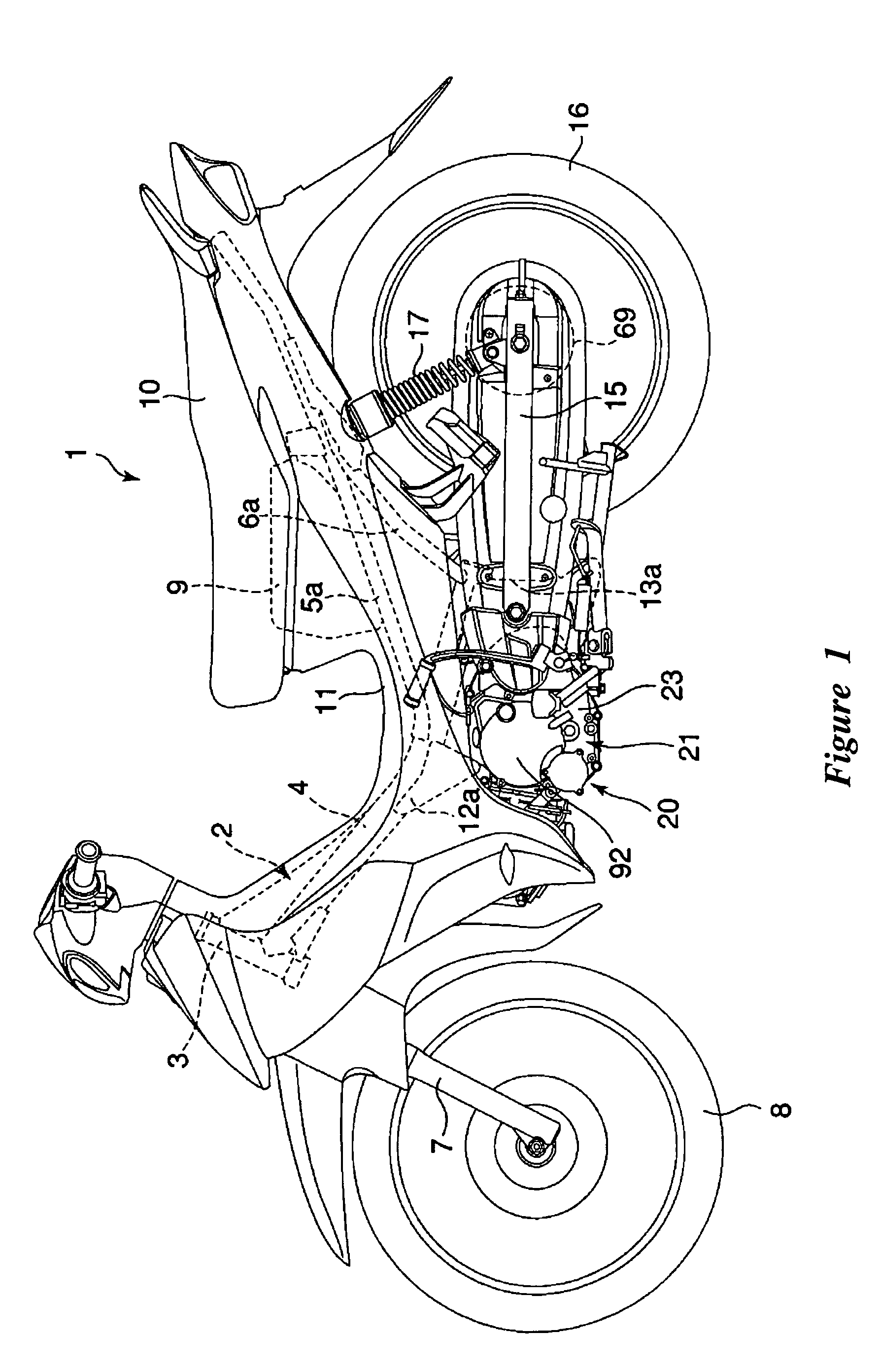
[0021] With reference initially to FIG. 1, a motorcycle 1 preferably comprises a backbone type frame 2. While the illustrated vehicle comprises a motorcycle or scooter, certain features, aspects and advantages of the present invention may also find utility with other types of vehicles. In particular, certain features, aspects and advantages of the present invention may find utility with other vehicles having a low slung engine that is supported by a central frame member.

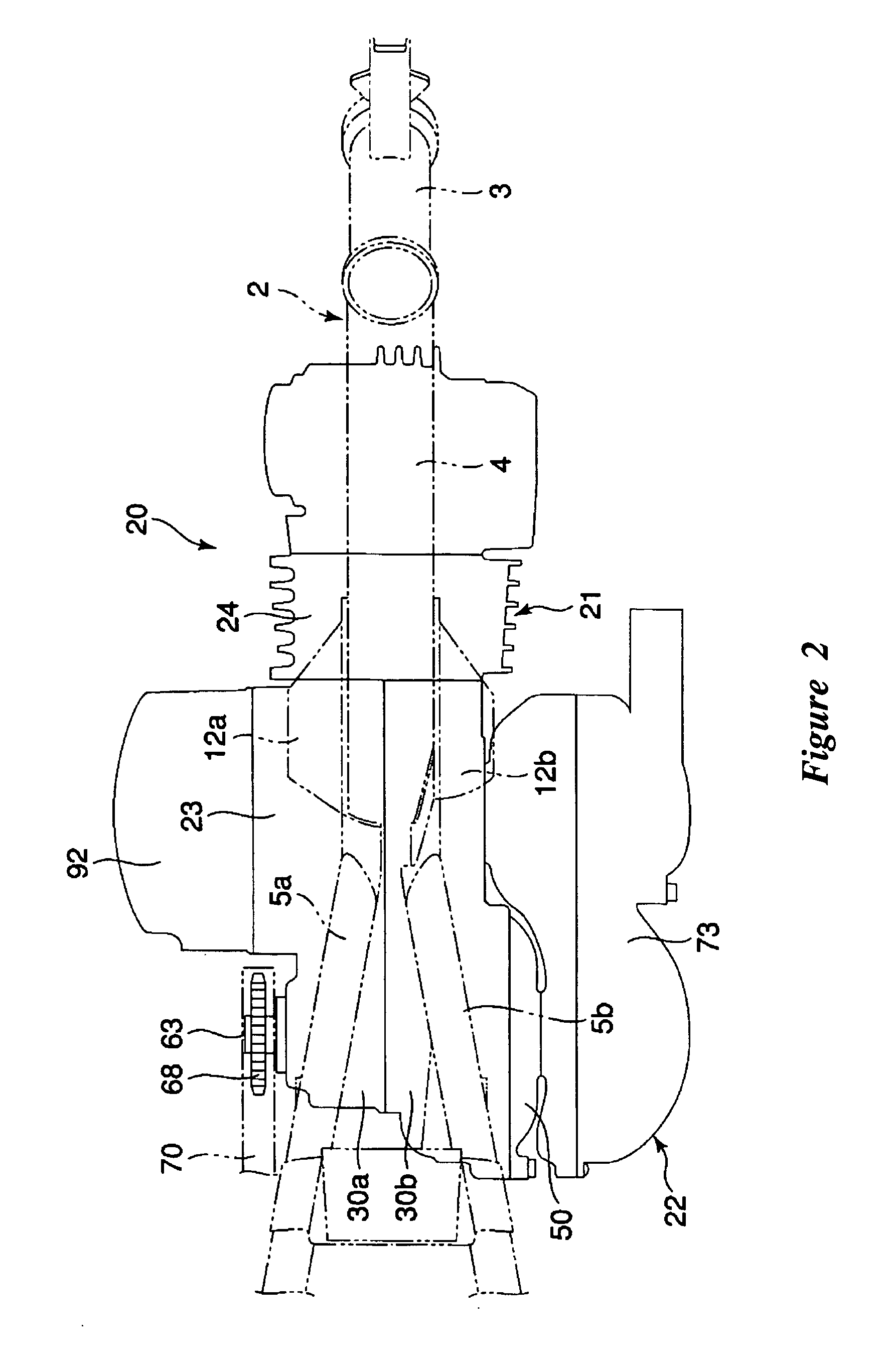
[0022] As illustrated, the steering head pipe 3 is located at the front end of the frame 2. The steering head pipe 3 supports a front wheel 8 via a front fork 7. A main frame member 4 extends rearward of the steering head pipe 3. The main frame member 4 can be secured to the steering head pipe 3 in any suitable manner. In one configuration, the main frame member 4 is welded to the steering head pipe 3. The main frame member 4 preferably defines the primary structure of the frame 2 and can be made of any suitable mat...


PUM


Abstract

A two wheeled vehicle has a frame assembly. The frame assembly comprises a backbone style frame. A power unit is mounted to the frame. A space is defined between the power unit and the frame such than an auxiliary component can be positioned within the space.

Description

CROSS-REFERENCE TO RELATED APPLICATIONS [0001] This application is a continuation-in-part of U.S. patent application Ser. No. 11 / 260,712, filed on Oct. 27, 2005 and titled MOTORCYCLE WITH LOWERED CENTER OF GRAVITY, which claimed the priority benefit of Japanese Application No. 2004-315,988 filed on Oct. 29, 2004, each of which is hereby incorporated by reference in its entirety. This application also claims the priority benefit of Japanese Application No. 2004-339,034, filed on Nov. 24, 2004, which is hereby incorporated by reference in its entirety.BACKGROUND OF THE INVENTION [0002] 1. Field of the Invention [0003] The present invention generally relates to a motorcycle or scooter comprising an engine suspended from a main frame member that extends rearward from a steering head pipe. [0004] 2. Description of the Related Art [0005] Motorcycles and scooters mainly used for commuting or business purpose generally comprise a backbone type frame. The frame comprises a steering head pipe...

Claims


Application Information

Patent Timeline
Patent Type & Authority Applications(United States)
IPC IPC(8): B62D61/02
CPCB62K2202/00B62M7/02
Inventor ISHIDA, YOUSUKEOISHI, AKIFUMI
Owner YAMAHA MOTOR CO LTD
Learn More