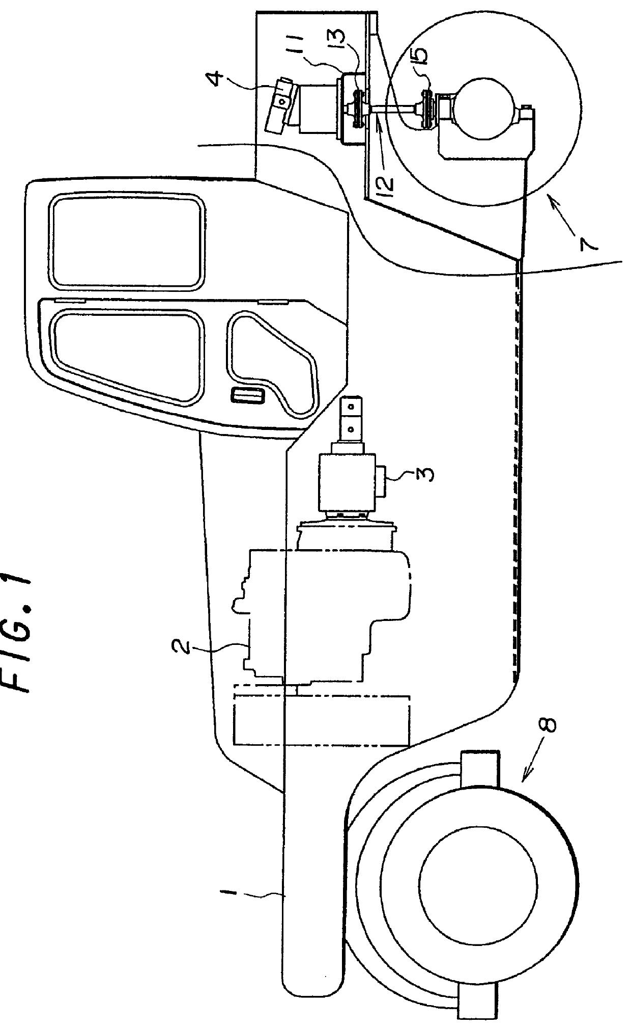
As the tired roller according to the present invention has adopted the above-described technical features, it brings about various advantageous effects. When the prime mover is operated to drive the hydraulic motor of the speed change unit via the hydraulic pump of the speed change unit, rotation of the hydraulic motor is transmitted to the propeller shaft so that the propeller shaft is rotated at a high speed with a low torque. After that, the rotation is reduced in speed by the
speed reduction mechanism on the output side of the propeller shaft and is transmitted, in a state increased in rotating torque, to the drive axle of the drive-axle tire train, whereby the tired roller of a heavy vehicle weight is allowed to travel without problems. As a drive mechanism for transmitting rotation of the hydraulic motor to the drive-axle tire train, the propeller shaft is used in place of a
chain drive mechanism which has heretofore been used. This has made it possible to avoid the kick-back-associated formation of a wave on a
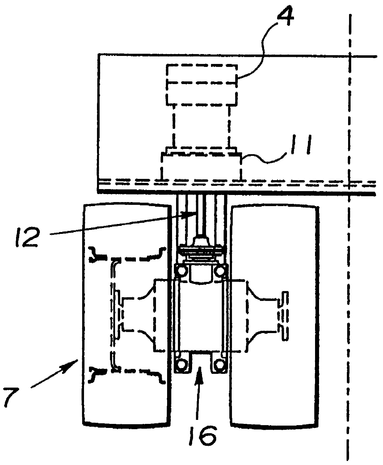
road surface under finishing by rolling compaction at the time of a start or stop of the tired roller, and further to obviate a chain tension adjustment. In addition, unlike the chain drive mechanism employed to date, the propeller shaft is rotated at a high speed with a low torque so that the propeller shaft can be formed smaller in
diameter. This has made it possible to easily arrange the propeller shaft in the narrow space between the adjacent tires in the drive-axle tire train.
. When the prime mover is operated to drive the hydraulic motor of the speed change unit via the hydraulic pump of the speed change unit, rotation of the hydraulic motor is transmitted to the propeller shaft so that the propeller shaft is rotated at a high speed with a low torque. After that, the rotation is reduced in speed by the
speed reduction mechanism on the output side of the propeller shaft and is transmitted, in a state increased in rotating torque, to the drive axle of the drive-axle tire train, whereby the tired roller of a heavy vehicle weight is allowed to travel without problems. As a drive mechanism for transmitting rotation of the hydraulic motor to the drive-axle tire train, the propeller shaft is used in place of a chain drive mechanism which has heretofore been used. This has made it possible to avoid the kick-back-associated formation of a wave on a
road surface under finishing by rolling compaction at the time of a start or stop of the tired roller, and further to obviate a chain tension adjustment. In addition, unlike the chain drive mechanism employed to date, the propeller shaft is rotated at a high speed with a low torque so that the propeller shaft can be formed smaller in
diameter. This has made it possible to easily arrange the propeller shaft in the narrow space between the adjacent tires in the drive-axle tire train.
Moreover, the use of the propeller shaft instead of a chain drive mechanism as the mechanism for transmitting rotation of the hydraulic motor to the drive axle of the drive-axle tire train can eliminate meshing
noise which would otherwise occur between the chain and its associated sprockets and would become a problem in urban areas, and can also obviate greasing the chain which would otherwise be required everyday. In addition, compared with use of a chain drive mechanism the
power transmission efficiency of which is not good, the use of the propeller shaft permits efficient transmission of power of the prime mover to the drive-axle tire train, thereby making it possible to reduce the fuel consumption of the prime mover.
In order to transmit rotation of the hydraulic motor to the drive axle of the drive-axle tire train at a speed reduced by the speed reduction mechanism, an axle provided with the drive axle of the drive-axle tire train may be arranged, and the axle may be provided with the speed reduction mechanism. This preferred embodiment can bring about the above-described basic advantageous effects, and can also bring about an advantageous effect that devices and equipments around the drive-axle tire train can be brought closer to each other and arranged in a compact space, the limited space of the tired roller can be effectively used, and maintenance and inspection work can be facilitated.
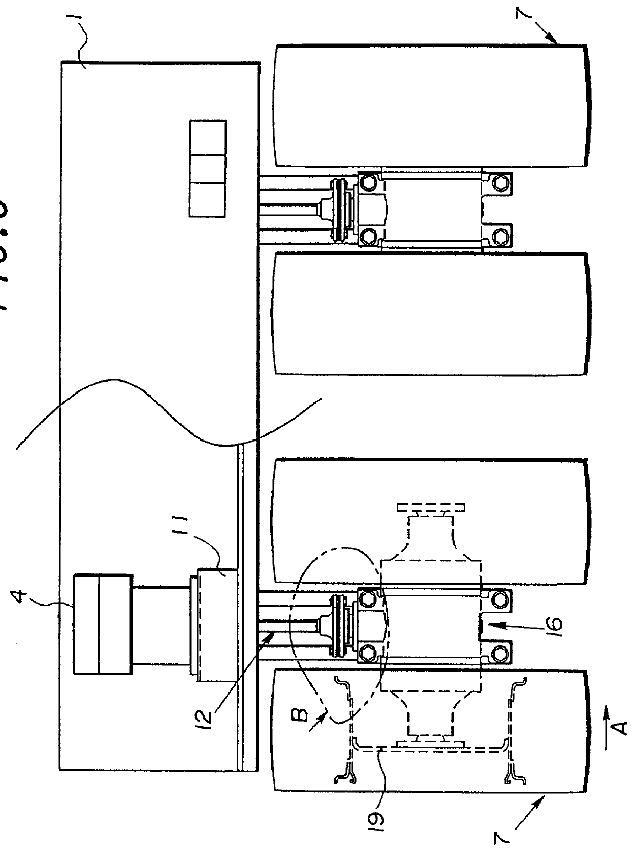
Preferably, the speed reduction mechanism may be constructed of a planetary gear speed-reduction mechanism, which is arranged concentrically with the drive axle of the drive-axle tire train, and a
gear transmission mechanism comprising a
bevel gear arranged on an input side of the planetary gear speed-reduction mechanism and a
pinion arranged on the output side of the propeller shaft and meshing with the
bevel gear, so that an axis of rotation to be transmitted from the propeller shaft to the drive axle of the drive-axle tire train may be changed in direction by the
gear transmission mechanism to extend in the same direction as an axis of the drive axle. This preferred embodiment can also bring about an additional advantageous effect that the speed reduction mechanism and direction changing mechanism can be conveniently arranged within a small space around the drive axle of the drive-axle tire train.
Desirably, the hydraulic motor may be arranged with an output shaft thereof extending downwardly, and accordingly, the propeller shaft may be arranged extending downwardly. This desired embodiment makes it possible to retain an ample space around the hydraulic motor in the tired roller main body and to reduce a
dead space, so that the overall volume of
water tanks can be increased.

