Method and apparatus for an electric meter

Active Publication Date: 2006-05-04
NETWORKED ENERGY SERVICES CORP
View PDF13 Cites 130 Cited by
  • Summary
  • Abstract
  • Description
  • Claims
  • Application Information

AI Technical Summary

Problems solved by technology

This is costly, time consuming, and did not occur on a continual basis.
This method of monitoring can also lead to a customer tampering with the utility providers' metering devices so as to create the appearance of not using as much of the utility as was actuall

Method used


Image

  • Method and apparatus for an electric meter
  • Method and apparatus for an electric meter
  • Method and apparatus for an electric meter

Examples


Embodiment Construction

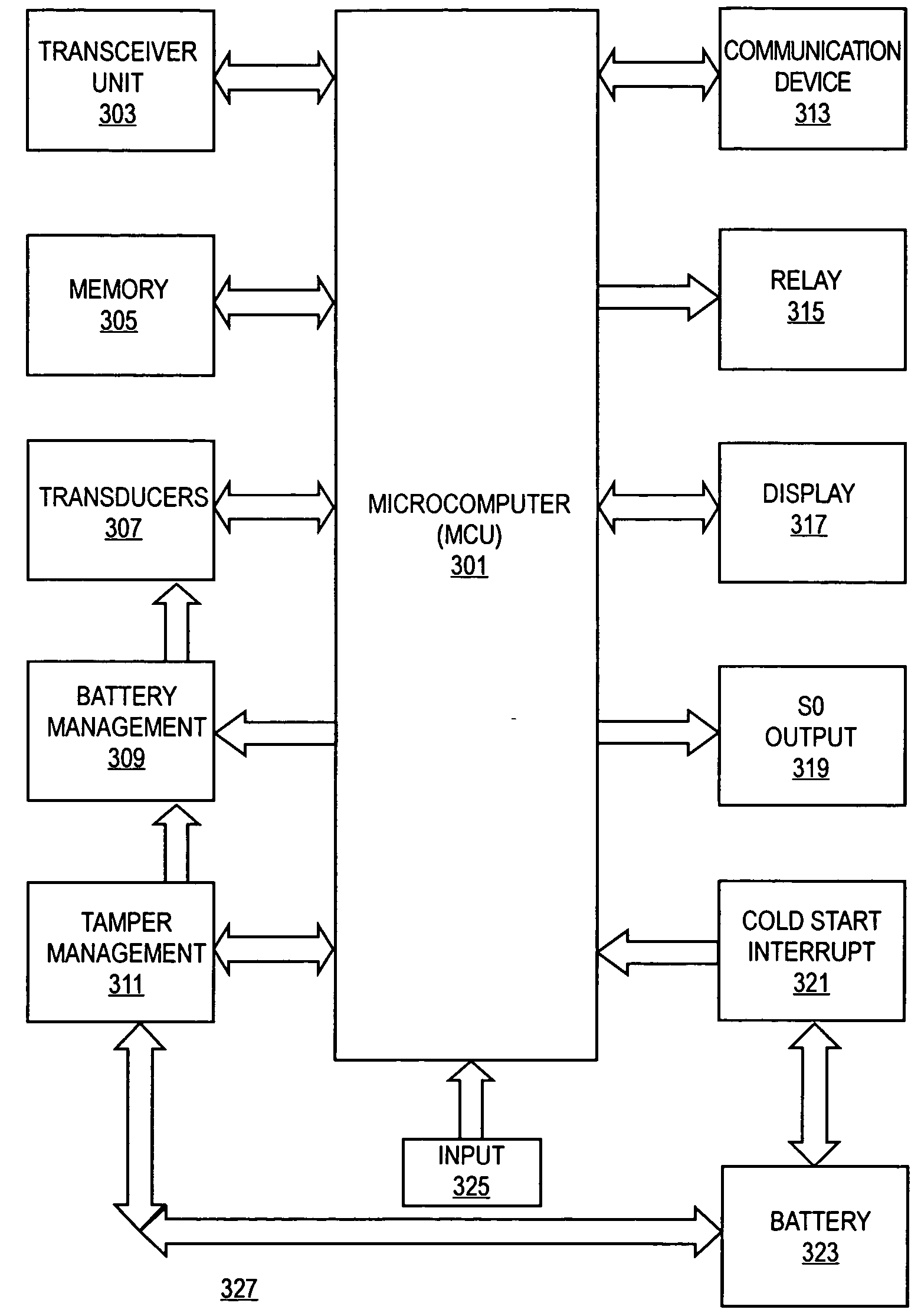
[0030] A meter for automatic meter reading and power line communication is described. In the following description, numerous specific details are set forth such as specific circuit components and associated potentials, in order to provide a thorough understanding of the present invention. It will be apparent to one skilled in the art, that the present invention may be practiced without these specific details. In other instances, well-known electrical circuit designs and implementations are not described in detail in order to not unnecessarily obscure the present invention.

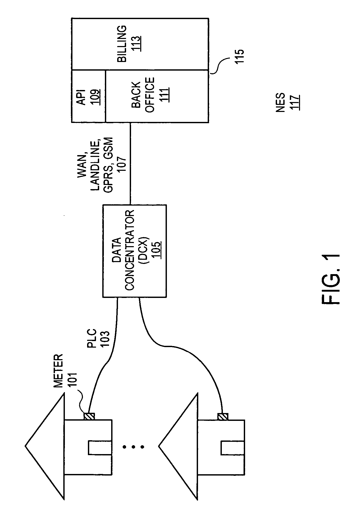
Meter as a Part of Networked Energy Services

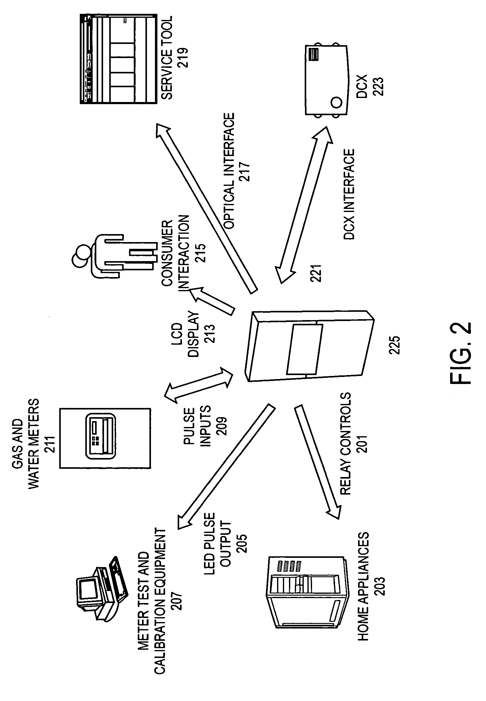
[0031] The meter of the present invention is a service provider to a larger system called networked energy services (NES). The meter in this system provides modern utilities with the tools that are needed to streamline their day-to-day metering operations. The meter is a solid-state electric energy meter capable of operation on worldwide voltage networks. Among the mai...


PUM


Abstract

An improved meter and its operation is described. The meter can be a part of a larger automated meter reading process that allows for remote reading of the meter though power line communication. Using a microcomputer core, the meter processes incoming analog data and can calculate several relevant data values need by utility providers. The meter can also be used to monitor and detect tampering dry connect/voltage free devices, such as gas and water meters, connected to the meter.

Description

BACKGROUND [0001] 1. Field of the Invention [0002] The present invention relates to the field of metering and metering communication systems. [0003] 2. Description of the Related Art [0004] Tracking and controlling energy consumption is a global concern. Utility providers, such as power, gas, and water, meter how much a particular customer uses over a period of time. Traditionally, the utility provider would have to physically send a person to the customer's location to read the meter to make this determination. This is costly, time consuming, and did not occur on a continual basis. This method of monitoring can also lead to a customer tampering with the utility providers' metering devices so as to create the appearance of not using as much of the utility as was actually used. [0005] In order to deal with these some of these pitfalls automatic meter reading (AMR) was developed. AMR is a technique of reading a meter remotely. One way of accomplishing this is to have the meter generat...

Claims


Application Information

Patent Timeline
IPC IPC(8): G01R19/00G08C15/06
CPCG01R21/133G01R22/066Y04S20/30
Inventor ROBINSON, ANDREW JOHNBACHOO, SPENCER SYDCUTURRUFO, CARLOS A.FICK, DARRON WERNERRILEY, GLEN MEYERSSUN, HAOQINGTEOMAN, DENIZWANG, MINGYUZYBURA, KATHRYN ANNE
Owner NETWORKED ENERGY SERVICES CORP
Why Eureka
Try Eureka