Liquid crystal display device

Inactive Publication Date: 2006-05-04
FUJITSU LTD
View PDF6 Cites 6 Cited by
  • Summary
  • Abstract
  • Description
  • Claims
  • Application Information

AI Technical Summary

Benefits of technology

[0012] The present invention has been made with the aim of solving the above problems, and it is an object of the present invention to provide a liquid crystal display device capable of reducing power consumption without causing display unevenness.
[0018] In the first and fourth aspects, the OFF timing of the light source does not agree with the end timing of the data scanning, but a predetermined time is provided from the end of the data scanning to the turn-off of the light source, whereby the display unevenness in the data scanning from the upstream toward the downstream is reduced. Further, in the first aspect, the light source is turned off before the end of the sub-frame, so that the deterioration in the displayed color due to the color mixture is not caused.
[0023] In the second and fifth aspects, the color display is performed by using the first driving system (in which the OFF timing of the light source and the end timing of the data scanning agree with each other) to decrease the light-emitting time of the light source, in case where the response time of the liquid crystal from the transmission state to the light-shielding state is sufficiently short, thereby attempting to reduce power consumption. On the other hand, in case where the response time of the liquid crystal from the transmission state to the light-shielding state is increased, the color display is performed by using the second driving system (in which the OFF timing of the light source and the end timing of the data scanning do not agree with each other) to switch the OFF timing of the light source to the timing considering the responsiveness of the liquid crystal, thereby reducing the display unevenness from the upstream toward the downstream of the data scanning.
[0028] In the third and sixth aspects, the light source is turned off during from the time that is after a while after the data scanning is ended to the time before the next sub-frame or next frame, whereby the display unevenness is surely prevented by providing a predetermined time from the end of the data scanning to the turn-off of the light source. Further, in the third aspect, the light source is turned off before the end of the sub-frame, so that light sources of different colors are not simultaneously turned on, and hence, the deterioration in the displayed color due to a color mixture is not caused.

Problems solved by technology

Since the reflection type liquid crystal display devices have poor visibility because the reflected light amount varies depending upon environmental conditions, transmission type color liquid crystal display devices using color filters are generally used as display devices of personal computers for displaying multi-color or full-color images.
For this reason, a lot of power is consumed by the backlight.
Moreover, since a color display is achieved using color filters, a single pixel needs to be composed of three sub-pixels, and there are problems that it is difficult to provide a high-resolution display, and the purity of the displayed colors is not sufficient.
However, in case where the OFF timing of the light source is made synchronism with the end timing of the second data scanning, a deterioration in responsiveness is caused due to a temperature fall in a liquid crystal display device using a liquid crystal material having spontaneous polarization, such as a ferroelectric liquid crystal or antiferroelectric liquid crystal having excellent responsiveness, thereby entailing a problem of high possibility of causing a display unevenness from the beginning region (upstream) of the data scanning to the last region (downstream) thereof.
The problem of the display unevenness is true not only for a field-sequential type liquid crystal display device but also for a color-filter type liquid crystal display device.

Method used


Image

  • Liquid crystal display device
  • Liquid crystal display device
  • Liquid crystal display device

Examples


first embodiment

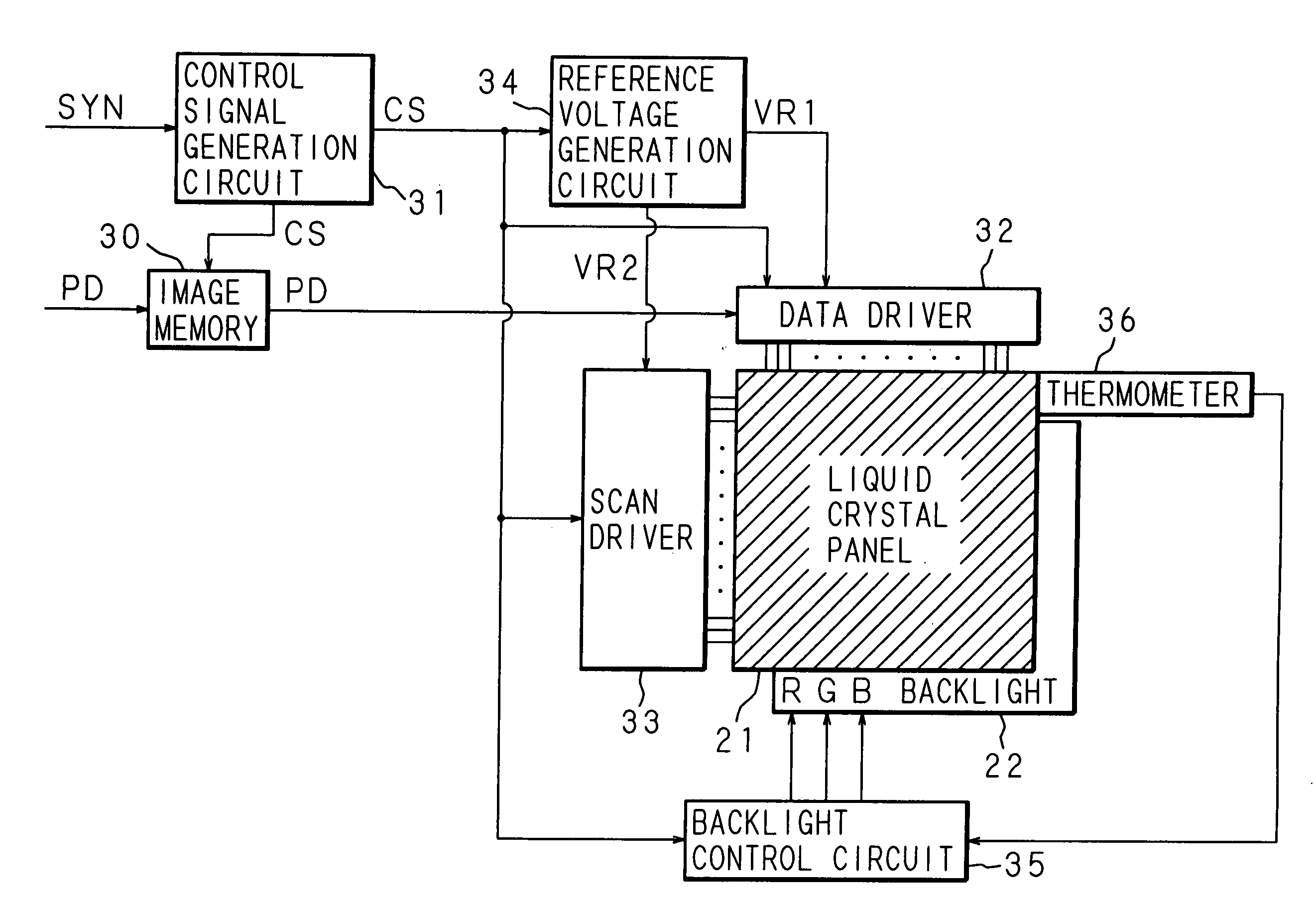
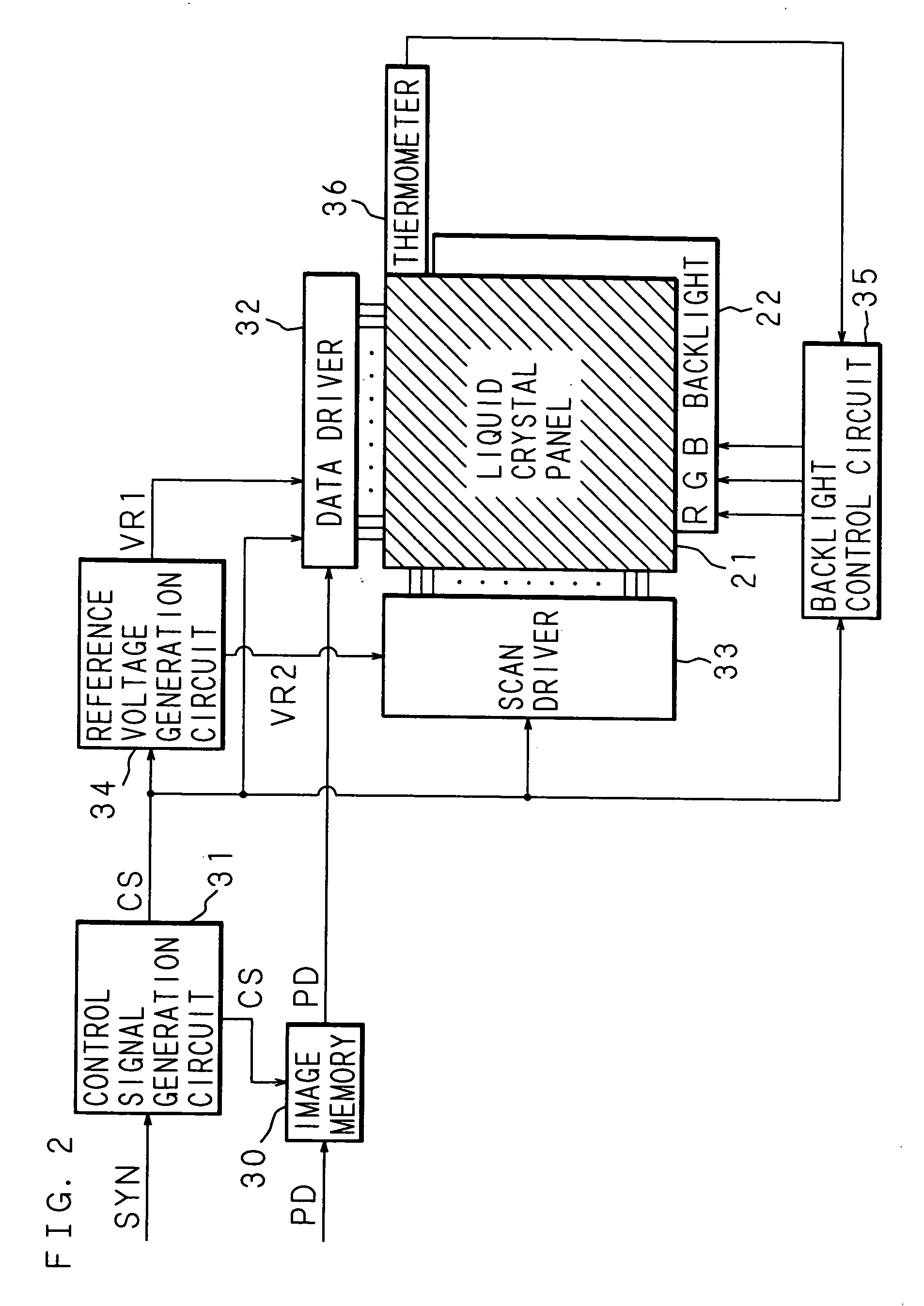
[0046]FIG. 2 is a block diagram showing the circuit structure of a liquid crystal display device according to the first embodiment of the present invention; FIG. 3 is a schematic cross sectional view of a liquid crystal panel and a backlight; and FIG. 4 is a schematic view showing an example of the overall structure of the liquid crystal display device.

[0047] In FIG. 2, the numerals 21 and 22 represent a liquid crystal panel and a backlight whose cross sectional structures are shown in FIG. 3. The backlight 22 is composed of an LED array 7 and a light guiding / diffusing plate 6. As shown in FIGS. 3 and 4, the liquid crystal panel 21 comprises a polarization film 1, a glass substrate 2, a common electrode 3, a glass substrate 4 and a polarization film 5, which are stacked in this order from the upper layer (front face) side to the lower layer (rear face) side, and pixel electrodes 40 which are arranged in matrix form on the common electrode 3 side of the glass substrate 4.

[0048] A d...

second embodiment

[0065]FIG. 9 is a block diagram showing the circuit structure of a liquid crystal display device according to the second embodiment. In FIG. 9, the same parts as in FIG. 2 are designated with the same numerals, and the explanation thereof is omitted.

[0066] In the aforesaid first embodiment, the switching of the drive sequence is made in accordance with the temperature of the liquid crystal panel 21. However, in this second embodiment, the switching of the drive sequence is made in accordance with the response time from the transmission state to the light-shielding state of the liquid crystal panel 21.

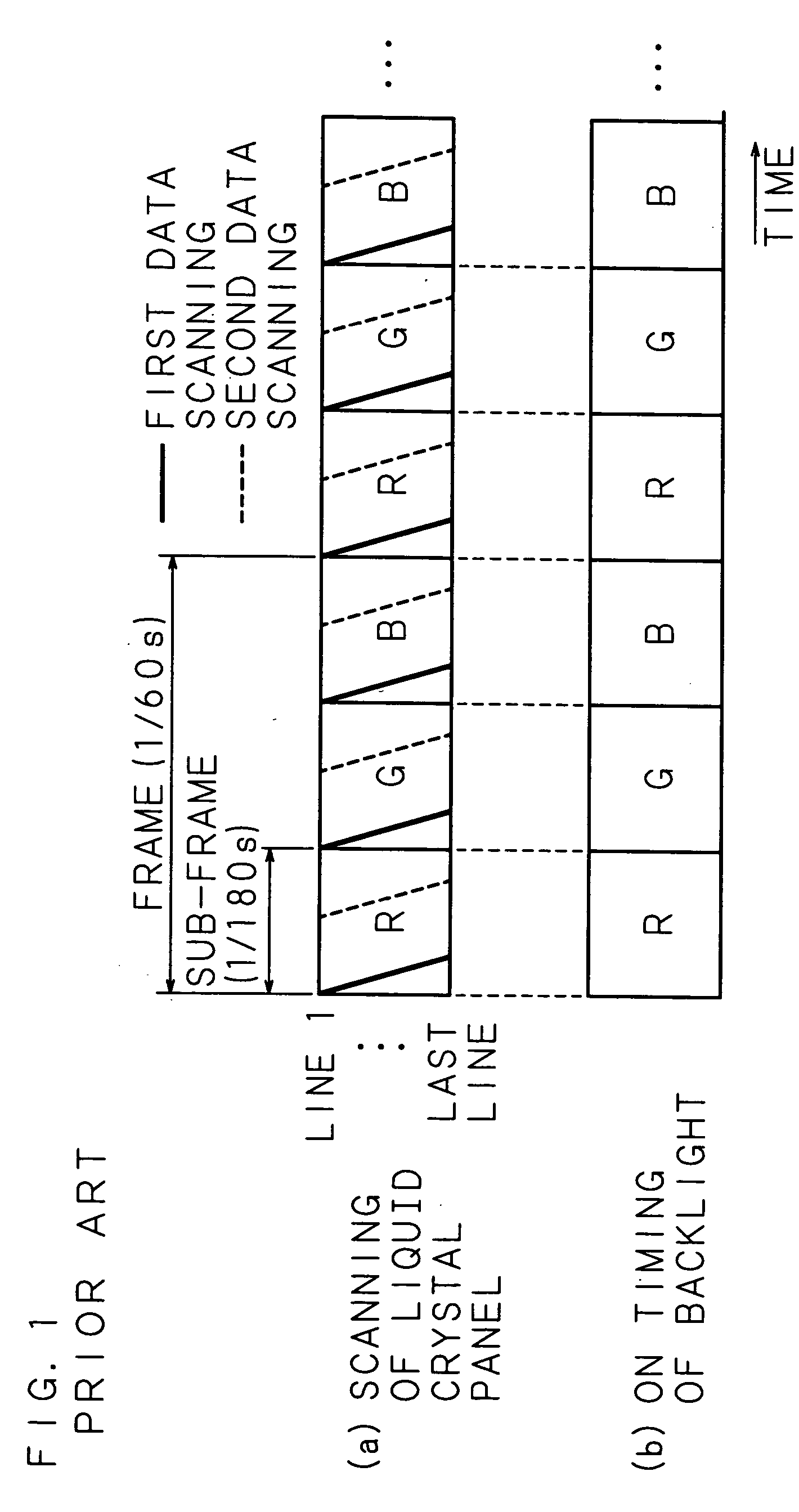
[0067] In FIG. 9, numeral 37 represents a photosensor provided to the liquid crystal panel 21. The photosensor 37 detects the response time from the transmission state to the light-shielding state of the liquid crystal panel 21, and outputs the detected result to the backlight control circuit 35. Specifically, the drive sequence (all turned on during sub-frame) shown in FIG. 1 is set ...


PUM


Abstract

A color display is performed by carrying out a switching between a first driving system in which the OFF timing of a light source and the end timing of a data scanning agree with each other and a second driving system in which the OFF timing of a light source and the end timing of a data scanning do not agree with each other. In case where a response time of a liquid crystal from a transmission state to a light-shielding state is sufficiently short, a color display is performed by using the first driving system to decrease a light-emitting time of a light source. On the other hand, in case where the response time of the liquid crystal from the transmission state to the light-shielding state is increased, a color display is performed by using the second driving system.

Description

[0001] This application is a continuation of PCT International Application No. PCT / JP2003 / 009893 which has an International filing date of Aug. 4, 2003, which designated the United States of America.TECHNICAL FIELD [0002] The present invention relates to field-sequential type or color-filter type liquid crystal display devices. BACKGROUND ART [0003] Along with the recent development of so-called information-oriented society, electronic apparatuses, such as personal computers and PDA (Personal Digital Assistants), have been widely used. With the spread of such electronic apparatuses, portable apparatuses that can be used in offices as well as outdoors have been used, and there are demands for small-size and light-weight of these apparatuses. Liquid crystal display devices are widely used as one of the means to satisfy such demands. Liquid crystal display devices not only achieve small size and light weight, but also include an indispensable technique in an attempt to achieve low powe...

Claims


Application Information

Patent Timeline
IPC IPC(8): G09G5/10G09G3/34
CPCG09G3/3406G09G2310/0235G09G2310/024G09G2310/061G09G2310/08G09G2320/041G09G2330/021
Inventor YOSHIHARA, TOSHIAKIMAKINO, TETSUYATADAKI, SHINJISHIROTO, HIRONORIKIYOTA, YOSHINORIKASAHARA, SHIGEOBETSUI, KEIICHI
Owner FUJITSU LTD
Why Eureka
Try Eureka