
Method of manufacturing display panel, display panel, and display device

a technology of display panel and encapsulation film, which is applied in the field of display technology, can solve the problems of reduced ability of encapsulation film to block moisture, high cost, and complicated process, and achieve the effect of improving the uniformity of brightness of the display panel and stabilizing the cathode voltage of the display panel

Active Publication Date: 2021-08-17
WUHAN CHINA STAR OPTOELECTRONICS SEMICON DISPLAY TECH CO LTD
View PDF6 Cites 0 Cited by
  • Summary
  • Abstract
  • Description
  • Claims
  • Application Information

AI Technical Summary

Benefits of technology

The method described in this patent improves the manufacturing of display panels by adding a patterned inorganic insulating layer to the auxiliary electrode of the display panel. This results in a more stable cathode voltage and better brightness uniformity. Additionally, the method reduces the complexity and cost of the manufacturing process.

Problems solved by technology

In the prior art, a display panel is manufactured by a conventional method, the display panel is unevenly displayed, and the ability of the encapsulation film to block moisture is reduced, and the process is complicated and the cost is high.

Method used


Image

  • Method of manufacturing display panel, display panel, and display device
  • Method of manufacturing display panel, display panel, and display device
  • Method of manufacturing display panel, display panel, and display device

Examples


Embodiment Construction

[0057]The technical solutions in the embodiments of the present invention are clearly and completely described in the following with reference to the accompanying drawings in the embodiments of the present invention. It is obvious that the described embodiments are only a part of the embodiments of the present invention, but not all embodiments. All other embodiments obtained by a person skilled in the art based on the embodiments of the present invention without creative efforts are within the scope of the present invention.

[0058]In the description of the present invention, it is to be understood that the terms “center”, “longitudinal,”“transverse,”“length,”“width,”“thickness,”“upper,”“lower,”“front,”“back,”“left,”“right,”“vertical,”“horizontal,”“top,”“bottom,”“inside,” and “outside” of orientational or positional relationship are based on the orientational or positional relationship shown in the drawings, and are merely for the convenience of describing the present invention and t...


PUM

PropertyMeasurementUnit
capacitanceaaaaaaaaaa
electroluminescentaaaaaaaaaa
areaaaaaaaaaaa

Abstract

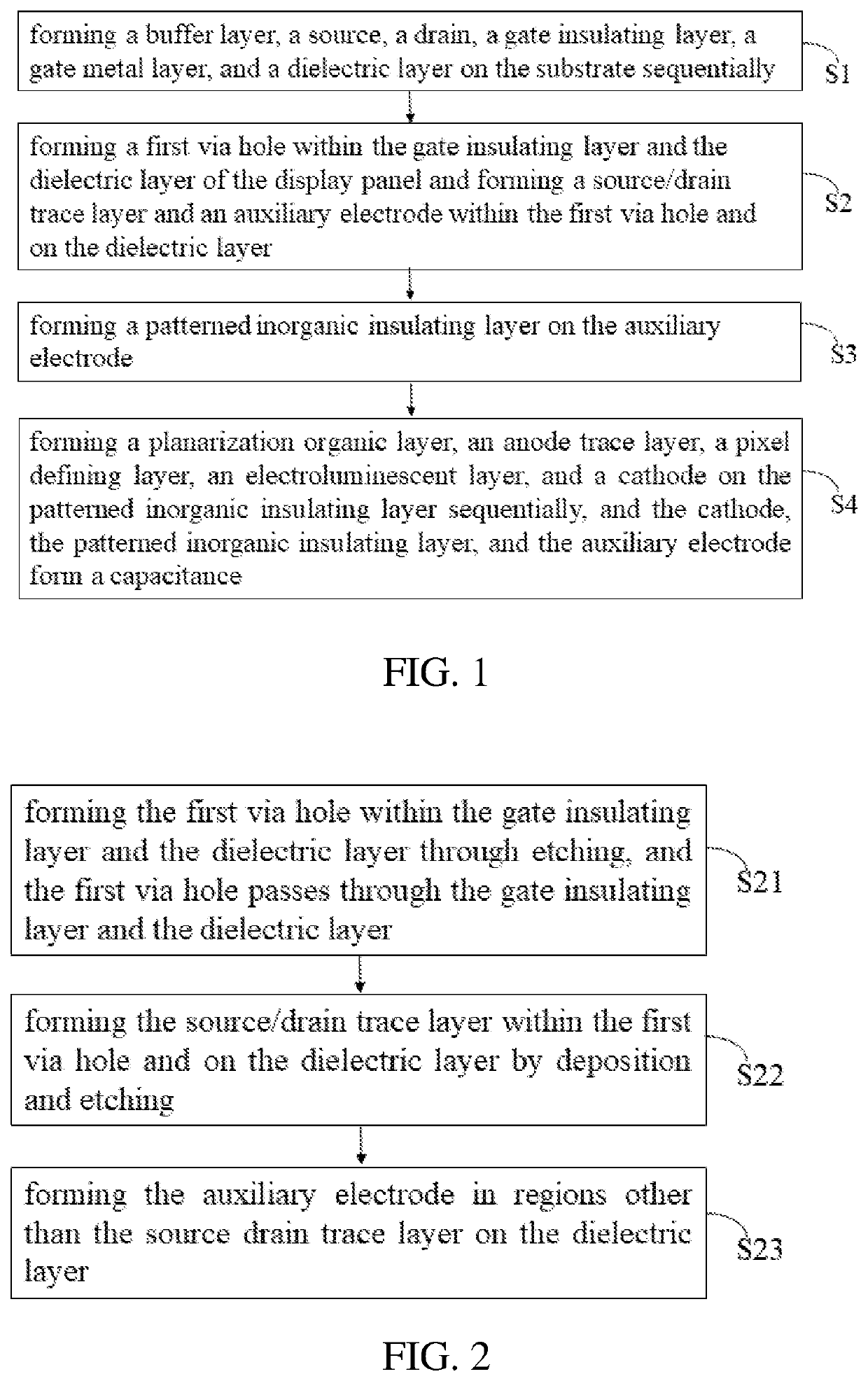
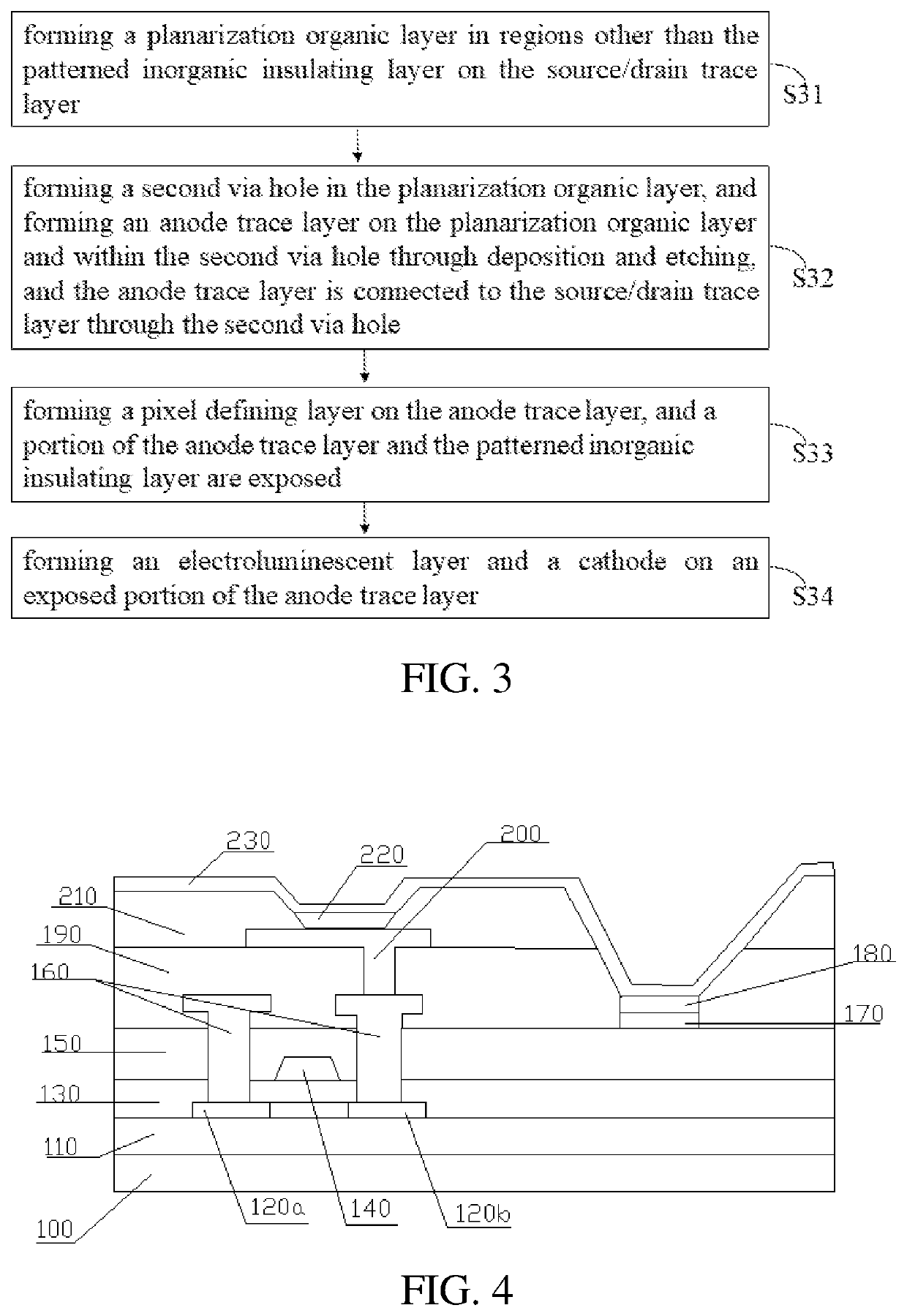
A method of manufacturing a display panel, the display panel, and a display device are provided. The method includes forming a first via hole within a gate insulating layer and a dielectric layer of the display panel, forming an auxiliary electrode within the first via hole and on the dielectric layer, forming an inorganic insulating layer on the auxiliary electrode, and forming a cathode on the inorganic insulating layer. The cathode, the inorganic insulating layer, and the auxiliary electrode form a capacitance. The method maintains stability of a cathode voltage of the display panel, thereby improving uniformity of brightness of the display panel.

Description

BACKGROUND OF INVENTIONField of Invention[0001]The present invention relates to the field of display technology, and more particularly, to a method of manufacturing a display panel, the display panel, and a display device.Description of Prior Art[0002]Organic light emitting diode (OLED) devices have a self-luminous characteristic, unlike thin film transistor (TFT) liquid crystal display (LCD) devices requiring backlights, so the OLED devices have high visibility and brightness, low voltage requirements, and high power-saving efficiency. In addition, the OLED devices have light weight, thin thickness, simple structure, and low cost, so they have become one of the most promising products in the 21st century.[0003]Vss signal of the OLED display panel is transmitted to a cathode layer of a front evaporation layer through a source / drain trace layer of a non-display region of the display panel, thereby supplying power to a pixel cathode of the display region. However, due to an influence ...

Claims


Application Information

Patent Timeline
Patent Type & Authority Patents(United States)
IPC IPC(8): H01L27/12H01L51/50H01L27/32
CPCH01L27/1248H01L27/127H01L27/3246H01L51/5012H01L27/1255H10K59/1216H10K59/1315H10K59/1201H10K59/80522H10K50/11H10K59/122
Inventor XIANG, MING
Owner WUHAN CHINA STAR OPTOELECTRONICS SEMICON DISPLAY TECH CO LTD
Learn More