Blower

Inactive Publication Date: 2006-05-04
SUN PLEASURE
View PDF15 Cites 13 Cited by
  • Summary
  • Abstract
  • Description
  • Claims
  • Application Information

AI Technical Summary

Benefits of technology

[0006] It is an object of the present invention to provide a blow

Problems solved by technology

Unfortunately, this configuration for a conventional blower suffers from some drawbacks, which include a high center of gravity, fast heating of the electric motor, slow heat dissipation, and appreciable wear and l

Method used


Image

  • Blower
  • Blower
  • Blower

Examples


Example

[0011] The following detailed description is of the best presently contemplated modes of carrying out the invention. This description is not to be taken in a limiting sense, but is made merely for the purpose of illustrating general principles of embodiments of the invention. The scope of the invention is best defined by the appended claims.

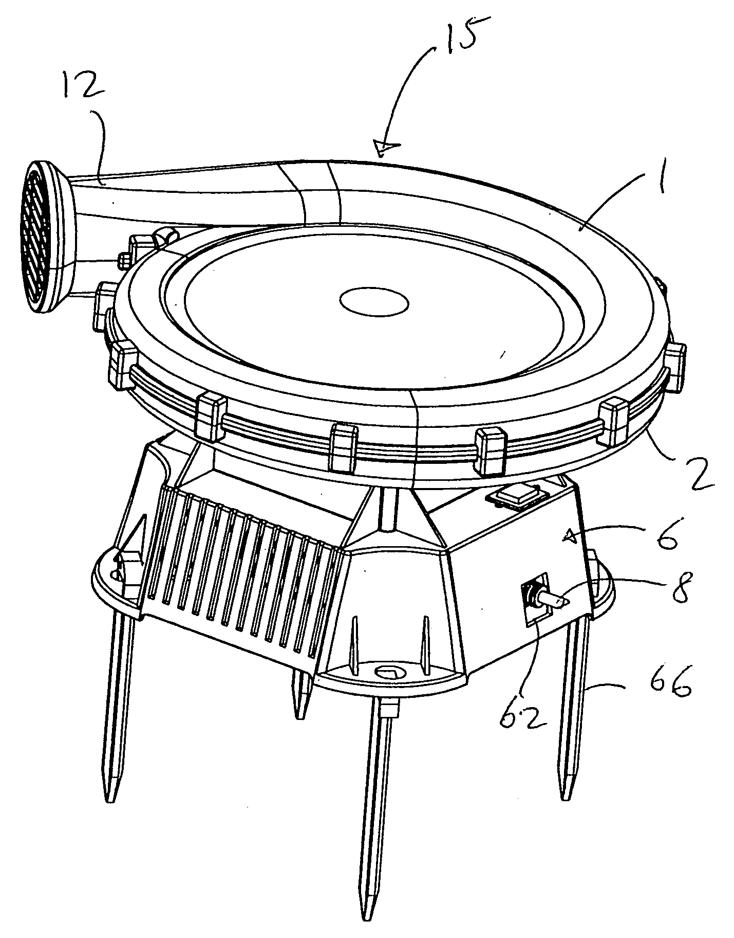
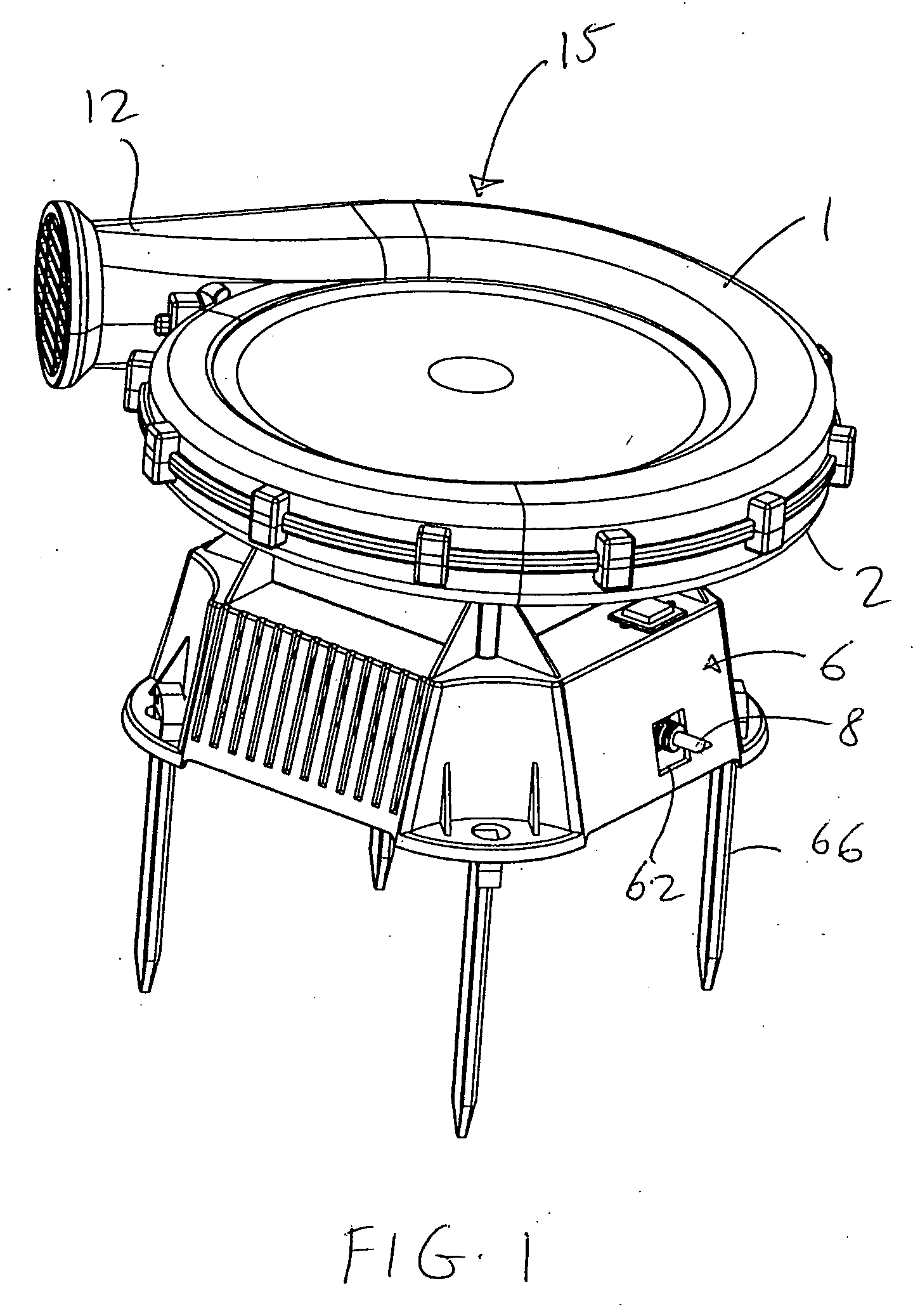
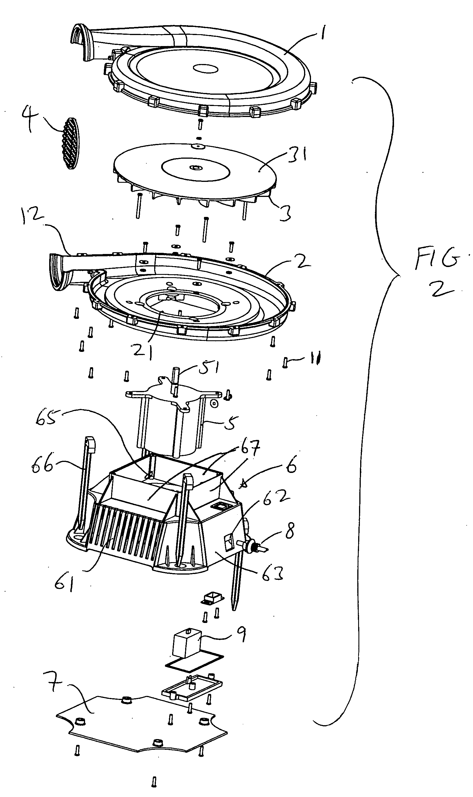
[0012] Referring to FIGS. 1-3, a blower according to the present invention has a base seat 6 that is mounted on a base plate 7. A capacitor 9 is provided inside the base seat 6, and is electrically coupled to a switch 8 that extends through an opening 62 in a side wall 63 of the base seat 6. An air inlet 61 is provided in one or more side walls 64 of the base seat 6. The base seat 6 also has an accomodation space 65 that is defined by four walls 67. The accomodation space 65 holds an electric motor 5. The motor 5 is coupled to the switch 8 and the capacitor 9 by wires (not shown). A plurality of stakes 66 are optional depending upon the location...


PUM


Abstract

A blower has an air channel housing that defines an air channel therein, the air channel housing having an air outlet extending therefrom. A plurality of air blades are positioned inside the air channel housing, and positioned horizontally with respect to a surface on which the blower is supported. A base seat is positioned below the air channel housing, the base seat having a side wall, with an air inlet provided in the side wall. A motor is positioned in the base seat and has a shaft that extends through the air channel housing to be coupled to the air blades.

Description

BACKGROUND OF THE INVENTION [0001] 1. Field of the Invention [0002] The present invention relates to a blower. [0003] 2. Description of the Prior Art [0004] A conventional blower is typically oriented so that the plane of its body stands vertically during use. The conventional blower typically includes an electric motor, air blades, and a centrifugal air channel. The air blades are oriented vertically in the air channel. The electric motor is positioned on one side of the air channel, and an air inlet is formed at the other side. When the power is turned on, the electric motor drives the air blades to rotate. After the air blades draw in air from the air inlet, the air is blown out through the air outlet of the air channel. [0005] Unfortunately, this configuration for a conventional blower suffers from some drawbacks, which include a high center of gravity, fast heating of the electric motor, slow heat dissipation, and appreciable wear and loss, which often results in a short servic...

Claims


Application Information

Patent Timeline
IPC IPC(8): F04B17/00F04B35/04
CPCF04D25/082F04D29/5806
Inventor LIANG, HESHENG
Owner SUN PLEASURE
Why Eureka
Try Eureka