Aiming arm for bone plates

a technology of bone plates and aiming arms, which is applied in the field of aiming arms for bone plates, can solve the problems of tedious adjustments, difficult adjustment, and many of these devices not being adjustable,

Active Publication Date: 2006-05-04
SYNTHES USA
View PDF8 Cites 225 Cited by
  • Summary
  • Abstract
  • Description
  • Claims
  • Application Information

AI Technical Summary

Benefits of technology

[0009] In a preferred embodiment, the tool guides have, at their heads, two radially-extending, diametrically-opposed knobs. The knobs may mate with two corresponding diametrically opposed slots formed in the inner surface of each of the bores of aiming arm. Thus, when positioned in the slots, the knobs prevent a tool guide from rotational movement relative to the bore and arm. The lock neutral guide may be placed within the bore in either of two possible positions. In one position, the eccentric channel (and sleeve) is offset from center in one direction and is therefore aligned with one side of a combination hole. In the other pos...

Problems solved by technology

Many of these devices are not adjustable.
Making these adjustments can be tedious and often requires trial and error.
Furthermore, even after a surgeon adjusts one of these devices, the alignment between the guide and a respective plate hole may be imprecise.
These problems become even more salient when the device being used is intended to align a ...

Method used


Image

  • Aiming arm for bone plates
  • Aiming arm for bone plates
  • Aiming arm for bone plates

Examples


Embodiment Construction

[0043] The aiming guide system is described below with reference to the illustrated embodiments. Those skilled in the art will recognize that numerous variations and modifications may be made without departing from the scope of the present invention. Accordingly, it should be understood that the embodiments of the invention described above are not intended as limitations on the scope of the invention, which is defined only by the claims.

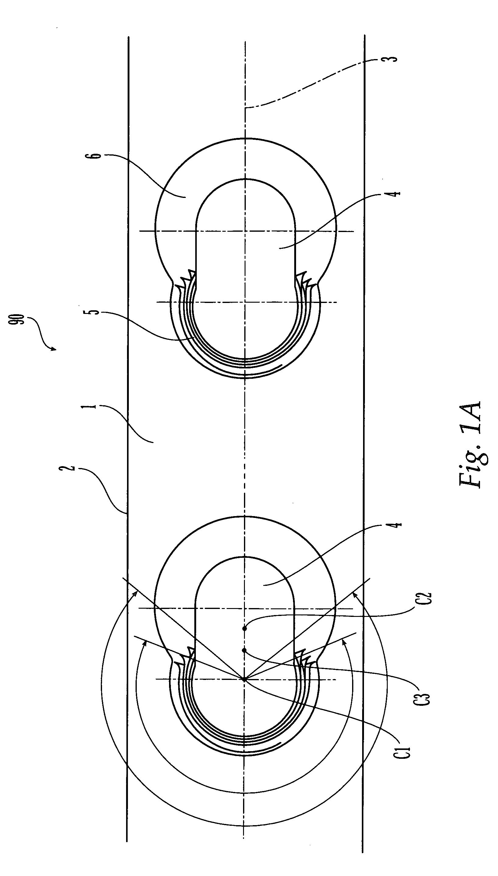
[0044]FIG. 1A illustrates one example of a section of a bone plate 90 having one illustrative embodiment of holes 4 with which the aiming guide system is intended to be used. FIG. 1A illustrates a bone plate 90 which includes an upper surface 1, a bone contacting or lower surface 2 (not shown), and a plurality of combination holes 4 extending through the upper surface 1 and lower surface 2. The holes 4 may be elongated (e.g., in a direction substantially aligned with a longitudinal axis of the plate) and may include a threaded portion 5 and a non-th...


PUM


Abstract

An aiming guide aligns a surgical tool with a hole in a bone plate. The aiming guide includes an arm portion having a longitudinal axis, top and bottom surfaces, and first and second ends. The aiming guide further includes a handle portion having upper and lower ends. The handle portion is, at its lower end, connected to the bone plate. The handle portion is, at its upper end, connected to the arm portion. Bores extend from the top surface to the lower surface of the arm portion. Each bore is configured and dimensioned to receive a tool guide in at least two different preset positions which locates the channel in at least two different hole positions. The bore includes two diametrically opposed slots extending along at least a portion of a length of the bore, the slots configured and dimensioned to mate with diametrically opposed knobs extending radially outward from a tool guide. The tool guide has a head and a sleeve portion, which has a centered channel. The sleeve portion and channel are eccentric with respect to the head portion. The tool guide is inserted in a first preset position in order to align a surgical tool with one portion of a two-portion bone plate hole, or in a second preset position rotated 180° from the first preset position, in order to align a surgical tool with the second portion of a two-portion bone plate hole.

Description

FIELD OF THE INVENTION [0001] The present invention relates to an apparatus for aligning surgical tools (e.g., drill bit, trochar) with a hole in bone plate. BACKGROUND OF THE INVENTION [0002] Surgical devices which align tools (e.g., drill bits, trochars) to bone plate holes are known in the art. Many of these devices are not adjustable. Some of these known devices can be adjusted by the surgeon or operator to tailor it for use with a number of different bone plates which have varying hole placement arrangements or patterns. These adjustable devices, however, require the surgeon or operator to manually adjust the guide to suit the particular plate being used. Making these adjustments can be tedious and often requires trial and error. Furthermore, even after a surgeon adjusts one of these devices, the alignment between the guide and a respective plate hole may be imprecise. These problems become even more salient when the device being used is intended to align a tool (e.g., a drill ...

Claims


Application Information

Patent Timeline
IPC IPC(8): A61B17/60
CPCA61B17/1728A61B17/8057A61B17/8014A61B17/17A61B17/58A61B17/60
Inventor GRADY, MARK P. JR.DIDOMENICO, SCOTTMAYO, KEITH A.MAST, JEFF W.BOLHOFNER, BRETT R.
Owner SYNTHES USA
Why Eureka
Try Eureka