Vented hollow plastic block

a hollow plastic block and hollow technology, applied in the field of transparent/translucent blocks, can solve the problems of insufficient structural strength of conventional wood frame construction to support glass blocks, difficult to create, and relatively heavy, and achieve the effect of avoiding imposing stresses

Inactive Publication Date: 2006-05-11
REGINA SAMUEL R
View PDF31 Cites 2 Cited by
  • Summary
  • Abstract
  • Description
  • Claims
  • Application Information

AI Technical Summary

Benefits of technology

[0009] The present invention is directed to ventilated transparent and / or translucent hollow plastic blocks having interlocking elements for rapidly building a wall or a wall section of such plastic blocks. Ventilation of the glass blocks to avoid imposing stresses on the walls of the glass blocks due to temperature changes and elevational changes is provided. In particular, equalization of pressure within each plastic block with the ambient pressure is provided by a single aperture disposed in the bottom edge of a mounted plastic block.
[0012] Yet another object of the present invention is to provide a ventilated plastic block having interlocking elements for rapid snap together assembly with adjacent plastic blocks.
[0014] A further object of the present invention is to provide a specifically located aperture in a translucent hollow plastic block to reduce the likelihood of condensation settling on the interior surfaces of the hollow plastic block.
[0016] A still further object of the present invention is to avoid creation of stresses in the side walls of a transparent / translucent hollow plastic block due to temperature and elevational changes.
[0017] A still further object of the present invention is to provide a method for avoiding stressing the side walls of a hollow plastic block due to temperature and elevational changes.

Problems solved by technology

Hollow glass blocks serve the sought end result very well but several difficulties are created.
First, the glass blocks are relatively heavy and generally are only permitted to be used under building codes in conjunction with supporting brick walls; conventional wood frame construction is generally considered of insufficient structural strength to support glass blocks.
Second, transport of the glass blocks from a point of manufacturer to the end user is generally expensive because of the weight and the attendant crating and shipping costs.
Third, in order to accommodate the change in pressure within the hollow part of the glass block due to temperature and elevational changes, the glass walls must be very thick.
Fourth, assembling a wall or wall section of glass blocks requires a skilled artesian to properly align the glass blocks and to exercise skill in securing the glass blocks to one another with a binding agent.
The pressure changes within the plastic blocks generally result in inward or outward flexing of the walls of the plastic block.
Such flexing creates stresses within the plastic material.
The resulting disfiguration becomes permanent and compromises the aesthetics of the wall or wall section formed of the plastic blocks.

Method used


Image

  • Vented hollow plastic block
  • Vented hollow plastic block
  • Vented hollow plastic block

Examples


Embodiment Construction

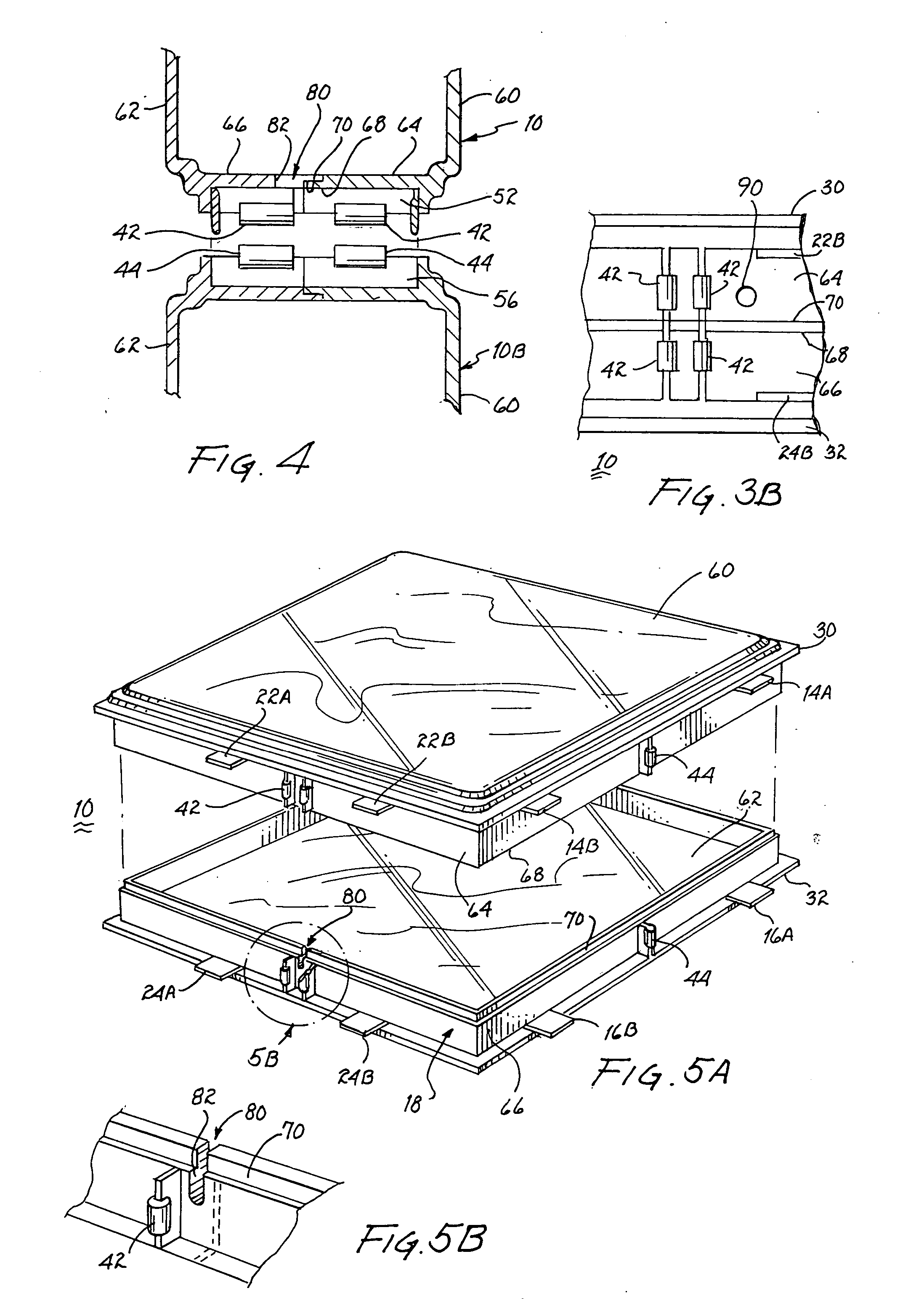
[0027] Interlocking unventilated plastic locks have been developed by the applicant, as illustrated and described in U.S. Pat. No. 5,836,125. The illustrations and writings contained therein are incorporated by reference herein. Accordingly, many of the features common with the present invention, particularly with respect to the interlocking and alignment elements, will be only summarily discussed as the details thereof are set forth in U.S. Pat. No. 5,836,125.

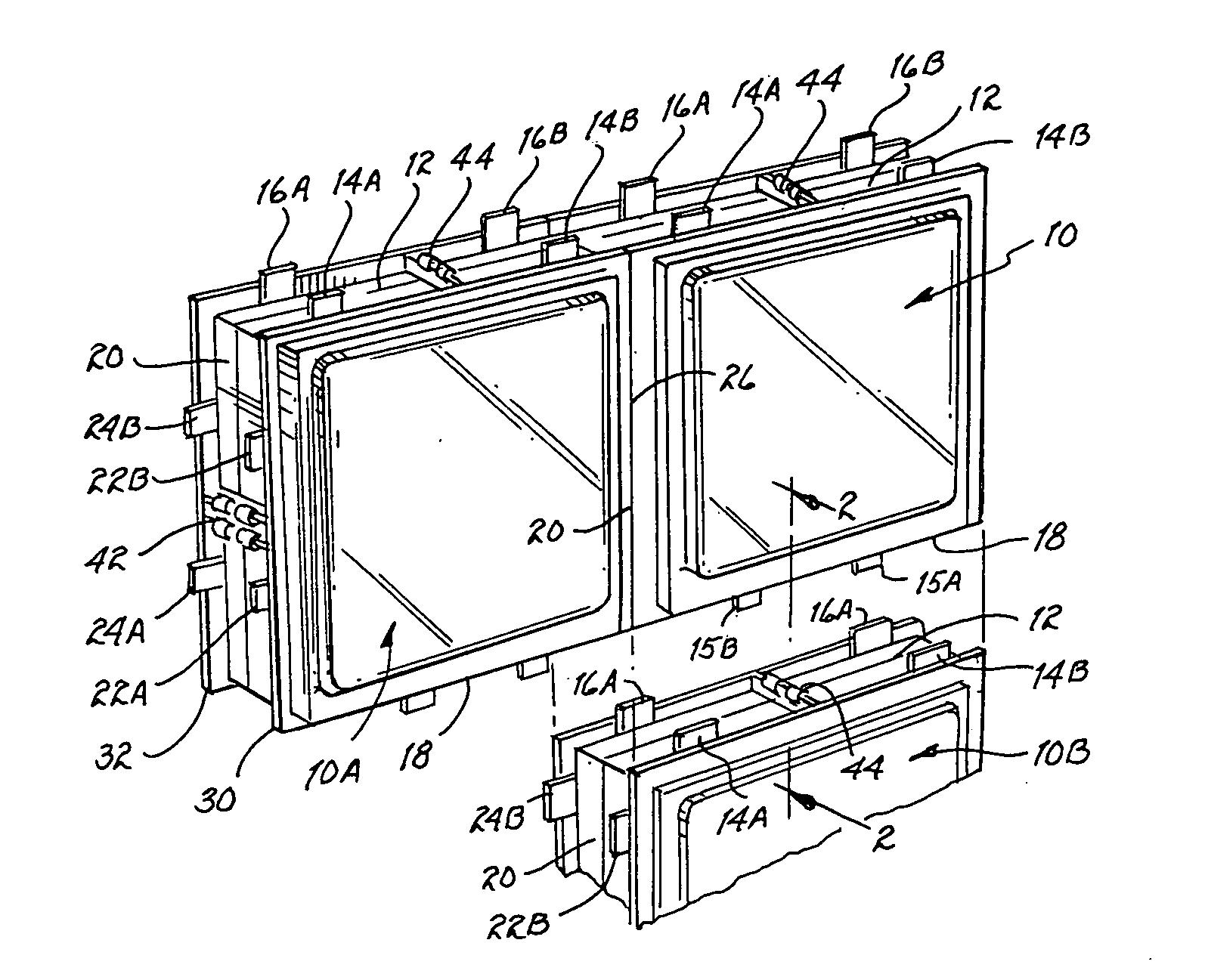
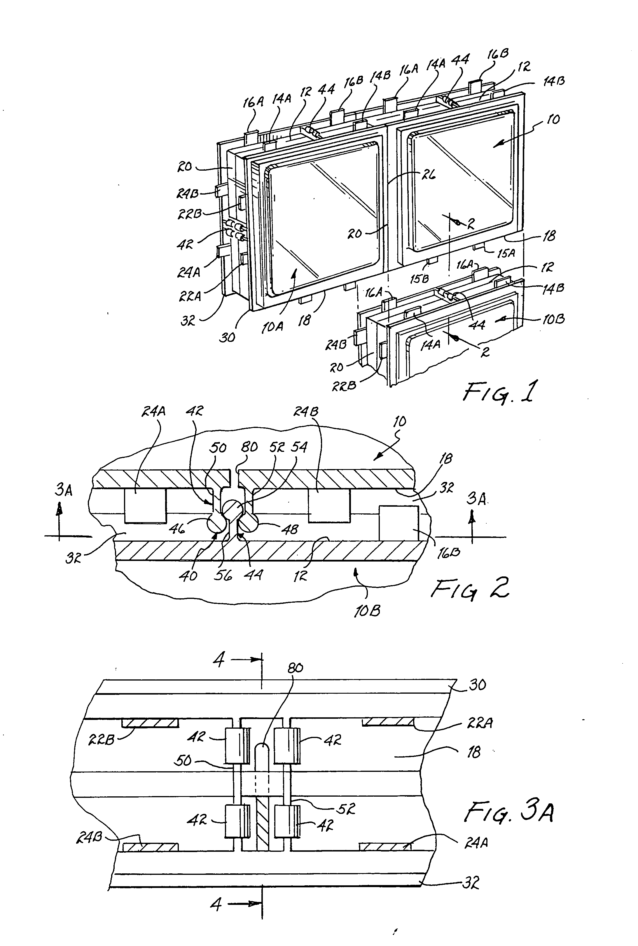
[0028] Referring to FIG. 1 there is shown a plurality of interlocking plastic blocks 10, 10A and 10B which are preferably, but not necessarily, of acrylic material. Edge 12 of each plastic block includes two pairs of alignment tabs 14A, 14B and 16A, 16B. The tabs of each pair of these pairs of tabs are relatively widely spaced from one another as illustrated. Opposite edge 18 of plastic block 10 includes two pairs of alignment tabs of which tabs 15A,15B are shown; these pairs of tabs are spaced closer to one another than pair...


PUM


Abstract

A vented hollow translucent / transparent plastic block for use in wall construction includes a single vent disposed along in a side wall of the plastic block for alleviating pressure within the plastic block and for discharging any condensation within the plastic block that may occur.

Description

CROSS REFERENCE TO RELATED APPLICATIONS [0001] The present application is a continuation application of an application entitled “Ventilated Interlocking Translucent Blocks”, filed May 8, 2002, assigned Ser. No. 10 / 142,306 and describing an invention by the present inventor.BACKGROUND OF THE INVENTION [0002] 1. Field of the Invention [0003] The present invention relates to transparent / translucent blocks as building materials used in commercial and residential construction and, more particularly, to ventilated interlocking blocks of manmade materials. [0004] 2. Description of Related Art [0005] For decades, hollow glass blocks have been used to form interior or exterior walls or sections thereof in order to permit transmission of light through such walls. Usually, these glass blocks distort any images viewed therethrough or the blocks may be translucent to permit passage of light and yet provide a significant degree of privacy. For example, glass blocks have been used as part of a bat...

Claims


Application Information

Patent Timeline
Patent Type & Authority Applications(United States)
IPC IPC(8): E04B5/04E04C1/42
CPCE04C1/42
Inventor REGINA, SAMUEL R.
Owner REGINA SAMUEL R
Why Eureka
Try Eureka