Adjustable rotation radius articulated joint for gym machines and knee tutors

a tutoring and adjustable technology, applied in the field of adjustable rotation radius articulated joints for gym machines and knee tutors, can solve the problems of complex knee articular mechanics, anomalous tension, compressive force, etc., and achieve the effect of avoiding the above-mentioned anomalous tension

Inactive Publication Date: 2002-02-28
PELLIS GIANCARLO
View PDF0 Cites 6 Cited by
  • Summary
  • Abstract
  • Description
  • Claims
  • Application Information

AI Technical Summary

Benefits of technology

[0044] The purpose of this invention is to provide users with an articulated joint number of rebound phenomena take place which are proportional to the load (weight P) and to the velocity with which the load itself is lifted. In order to avoid exerting these stresses, especially in patients who have just undergone surgery in the crossed ligaments, the lower part of the leg should also be bound in several points by some sort of sling (see FIG. 7), so as to make it as integral as possible to mobile load arm L. The latter, which is hinged to the frame of the weight-lifting machine, releases rebound phenomena on the central rotation pin, thereby sparing the crossed ligaments.
[0046] In this specific sector some devices are known to exist that are capable of reducing the tensile stresses exerted on the leg. The one described in U.S. Pat. No. 5,020,797 is aimed at allowing a leg injured in the knee to exercise, by applying a resistance force onto the leg. The leg can be extended against this resistance in a given direction, at the same time it is able to prevent a sub-dislocation in another direction close to the abovementioned knee.
[0051] Indeed, this patent enables the tibia to advance "properly" in the extension movement which turns out to have been "proper" only when the starting position is "improper", that is to say if the centre of the knee is set back (but not excessively so) with reference to the centre of the machine. Should the centre of the knee be casually placed (indeed, no description of how to identify it is available) and therefore be aligned to the centre of the machine or advanced, the above mentioned system brings about the advancement of the tibia and exerts a stress on the fore crossed ligament. Another device known to exist is described in the French Model No. 83 13474 published under No. 2.550.708, which allows the reduction of the pressure in the knee's joint when exercising the quadriceps muscles. This device features an arm endowed with weights pivoted onto a joint, a horizontal shaft that passes through the joint itself and a resistance arm. Special slings keep the patient still on a chair so that the joints of one knee are fastened. The usual rod of the resistance arm is replaced by a special fastening shoe which features fastening strips whereby the patient's foot is locked to the shoe itself. The latter is locked onto a staff which is connected to the free end of an arm that constitutes a part of a three-arm lever that can rotate around the shaft.
[0054] Hence, a traction occurs in the longitudinal direction of the lower part of the leg. Thus the pressure in the articulation of the knee diminishes and no pain is felt in the knee when taking exercise. The traction is brought about automatically when the patient extends the leg or moves the lower part of it around the articulation of the knee. The width and the variation of this traction depend both from the characteristics of the elastic component and from the distance between, on the one hand, the trajectory of a point that coincides with the fastening elements of the lower part in the patient's leg rotating around the articulation of the knee, and, on the other, the trajectory of a point that coincides with the immobilising shoe rotating around the axis of the same joint (that is to say, the distance of the position of the rotation axis of the resistance arm with reference to the position of the articulation of the knee).
[0055] By placing the rotation axis of the resistance arm of this training device forward and above the articulation of the knee, it is possible to vary the traction curve in such a way that the maximum traction is achieved for a preestablished position (angular) in the movement between the position wherein the knee is completely bent (90.degree.) and the one wherein it is completely extended (0.degree.).
[0062] Furthermore, the definition of an efficient methodology enables the correct identification of the trajectory made by the knee in the flex-extension, a trajectory which must surely be accompanied by a drawing of the articular surfaces of the tibia and femur and the succession whereby the rotation and sliding movements are combined.

Problems solved by technology

The articular mechanics of the knee is therefore complex, and the type of movement that is made is in direct relation to the angle at which the knee is open.
These mechanical devices, which are thus bound to the limb, are hinged to an articulated joint which generally has a fixed center of rotation and which therefore is unable to provide the combined sliding and rotating movements and change the center of rotation, thereby producing anomalous tensions.
Indeed, as previously described, the leg reduces its radius when it flexes (the above mentioned R.sub.B-R.sub.A); this causes the mechanical device to rub against the leg, bringing about a friction which is passed on to the belts of the sling and results in a compressive force.
Knee tutors featuring a double centre of rotation are rather common; however in the positions ranging between 0.degree. and 30.degree. and between 90.degree. and 135.degree. they do not conform to the knee's mechanical physiology.
These mechanical devices, which are thus bound to the limb, are hinged to an articulated joint which generally has a fixed centre of rotation and which therefore is unable to provide the combined sliding and rotating movements and change the centre of rotation, thereby producing anomalous tensions.
Indeed, as previously described, the leg reduces its radius when it flexes (the above mentioned RB-RA); this causes the mechanical device to rub against the leg, bringing about a friction which is passed on to the belts of the sling and results in a compressive force.
Knee tutors featuring a double centre of rotation are rather common; however in the positions ranging between 0.degree. and 30.degree. and between 90.degree. and 135.degree. they do not conform to the knee's mechanical physiology.
However, there is no prior identification of the centre of the knee; this centre ought to be aligned with the central shaft.
The major flaw in the machines currently on the market lies in the fact that the leg sling (FIG. 7) cannot be made to rotate around a fixed centre because the knee, as previously stated, has no single centre of rotation and therefore cannot, as it moves, run along a circular path, but rather must perform a spiralling movement towards the centre.
The problem then consists in accompanying the knee while it moves without allowing other mechanical stresses to interfere in its movement.

Method used


Image

  • Adjustable rotation radius articulated joint for gym machines and knee tutors
  • Adjustable rotation radius articulated joint for gym machines and knee tutors
  • Adjustable rotation radius articulated joint for gym machines and knee tutors

Examples


Embodiment Construction

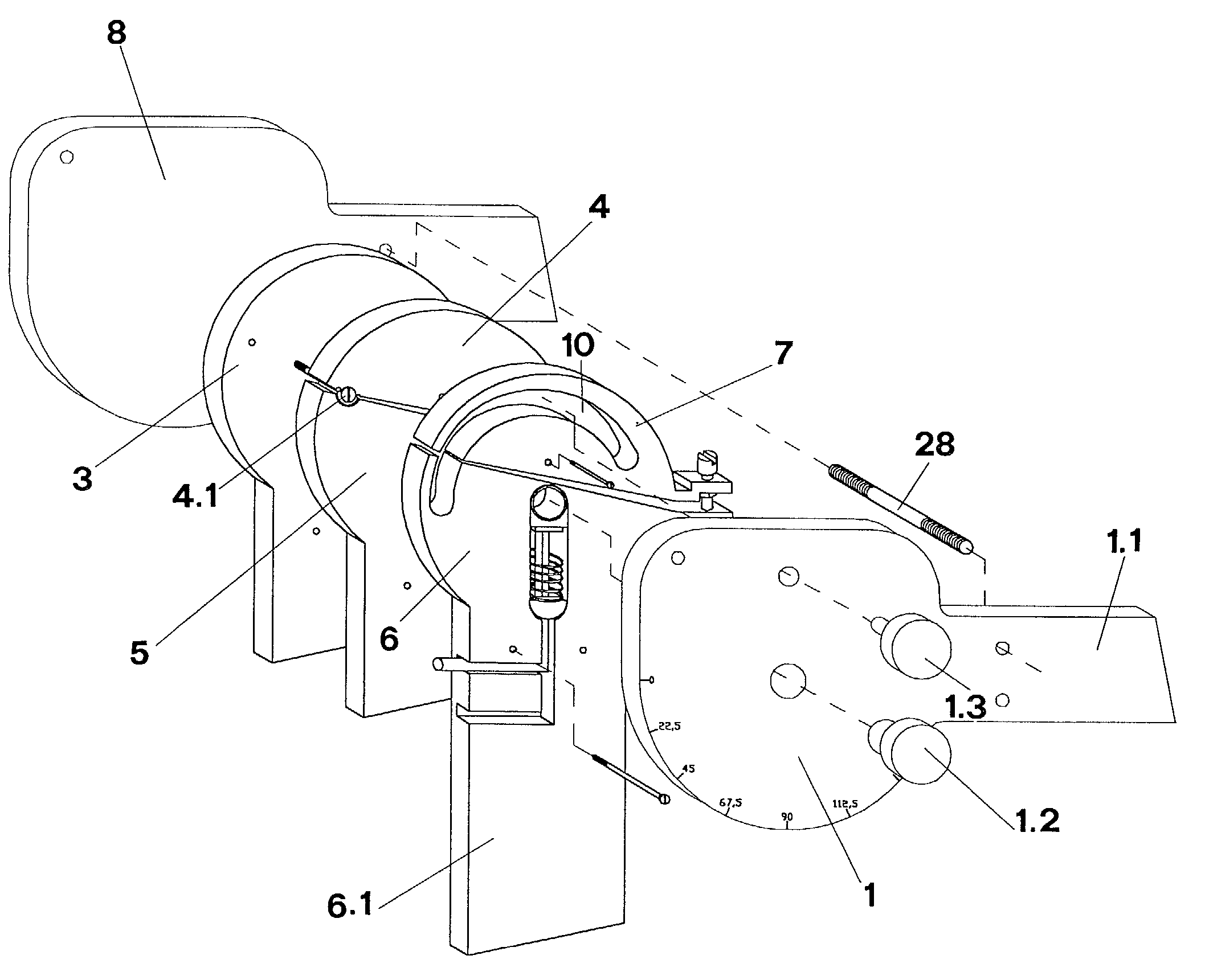
[0147] More precisely, in a first, simplified configuration applied to a leg extension weight-lifting machine with a resistance (P) constrained to mobile arm L, the articulated joint is formed by two plates 1 and 2; plate 1 is fastened to the weight-lifting machine by means of a bar 1.1, while plate 2 is able to rotate onto plate 1 with reference to a horizontal axis which passes through the femoral condyles of the subject when seated. An arm 2.1, featuring a horizontal rod located at the farther end and connected to the weights, is fastened to plate 2.

[0148] Plate 2 features two openings 2.2 and 2.3 at a right angle to the rotation surfaces of the two plates. The first opening 2.2 is rectangular in shape and the shorter sides are rounded; this opening is made by extending an ideal hole 2.4, which is located at the centre of plate 2, towards the outside along a radius defined as "a" which constitutes the longitudinal axis of symmetry of mobile arm 2.1.

[0149] The ends of the second o...


PUM


Abstract

This invention can be profitably employed in the fields of medicine and sports in the machines used to strengthen the muscles of the knee and in knee tutors. In its simplest version, the articulated joint is formed by two plates (1, 2) which can move freely on one another; alternatively, one plate (1) or the other (2) can be fastened to a fixed structure by means of a fastener. One of the plates features two openings (2.2, 2.3), where the first (2.2) is located at the center of a plate and is shaped like a rectangle. The second opening (2.3) has a specific shape: at first it is a circumference whose radius is equal to "I"; subsequently, it is a spiral which returns towards the center of the plate (2). The other plate features two pins (1.2 and 1.3), located at a distance "I"; the first pin (1.2) is located in the central position and is inserted into opening the (2.2); the second pin (1.3) is in a peripheral position and is located in the second opening (2.3). Alternatively the plate (2) can be replaced by several overlapping plates (3, 4, 5, 6, 7); the semi-plates are arranged in overlapping couples (4, 7 and 5, 6). The semi-plates (4, 7) are fastened to the plate (3) by means of a pin (4.1) placed in an ideal point of rotation (11) and are therefore free to rotate onto the semi-plates (5, 6).

Description

[0001] This invention can be profitably employed in the fields of medicine and sports as it is an indispensable component of knee tutors and of machines used to strengthen or in rehabilitation to restore the muscles of the knee to their former healthy condition.[0002] The knee is the intermediate articulation of the lower limbs. The movement whereby the knee is extended, or rather, the movement of extending the leg from the thigh is performed by means of the quadricep muscle, which is inserted in the foretuberosity of the tibia, a couple of centimeters below the knee. The movement of bending the knee, that is to say the movement of flexing the leg from the thigh is performed by means of the hind muscles of the thigh, as illustrated in FIG. 1. The flex / extension movement is always executed at the fore-hind level.[0003] The articular surfaces that come into contact in the knee are the femoral condyles (the distal, i.e. farther, part of the femur), and the tibia plate (the proximal, i....

Claims


Application Information

Patent Timeline
Patent Type & Authority Applications(United States)
IPC IPC(8): A61F5/01A63B23/08A61H1/02A63B23/04
CPCA61F5/0123A61F2005/0137A61H1/024A63B23/0494A63B21/065A63B21/1423A63B21/1449A63B21/00178A63B21/00069A63B21/1476A63B21/4011A63B21/4039A63B21/4025
Inventor PELLIS, GIANCARLO
Owner PELLIS GIANCARLO
Why Eureka
Try Eureka