Pressure plate assembly for a friction clutch

a technology of friction clutches and pressure plates, applied in the field of friction clutches, can solve the problems of increasing stress and rapid fatigue of leaf spring arrangements

Inactive Publication Date: 2002-06-06
ZF SACHS AG
View PDF0 Cites 2 Cited by
  • Summary
  • Abstract
  • Description
  • Claims
  • Application Information

AI Technical Summary

Problems solved by technology

This type of contact can lead to an increase in stress and t...

Method used


Image

  • Pressure plate assembly for a friction clutch
  • Pressure plate assembly for a friction clutch
  • Pressure plate assembly for a friction clutch

Examples


Embodiment Construction

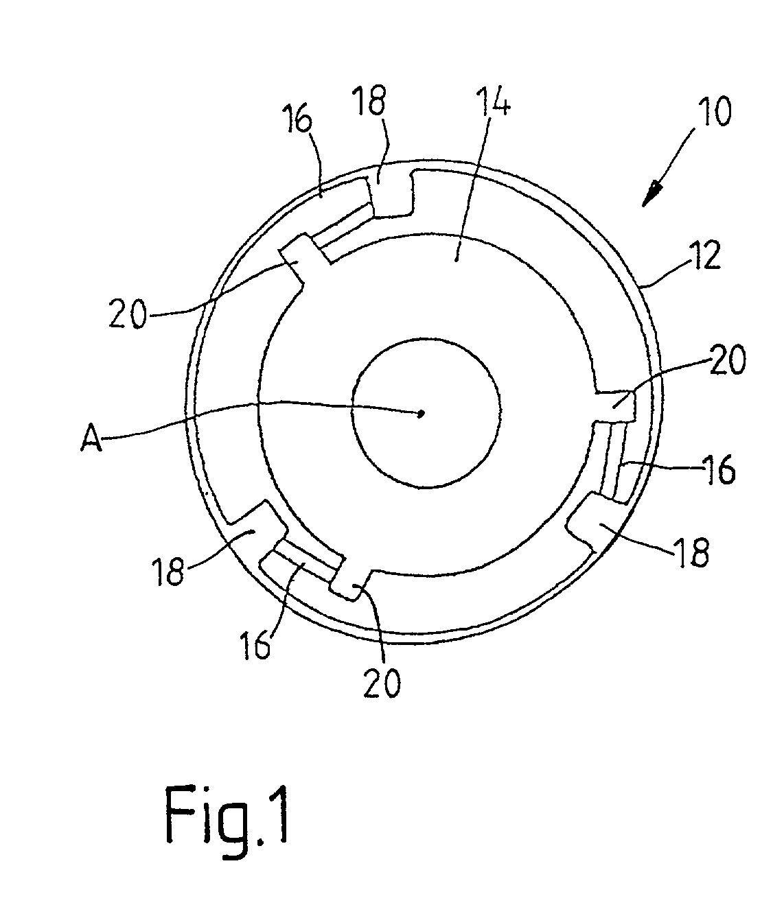
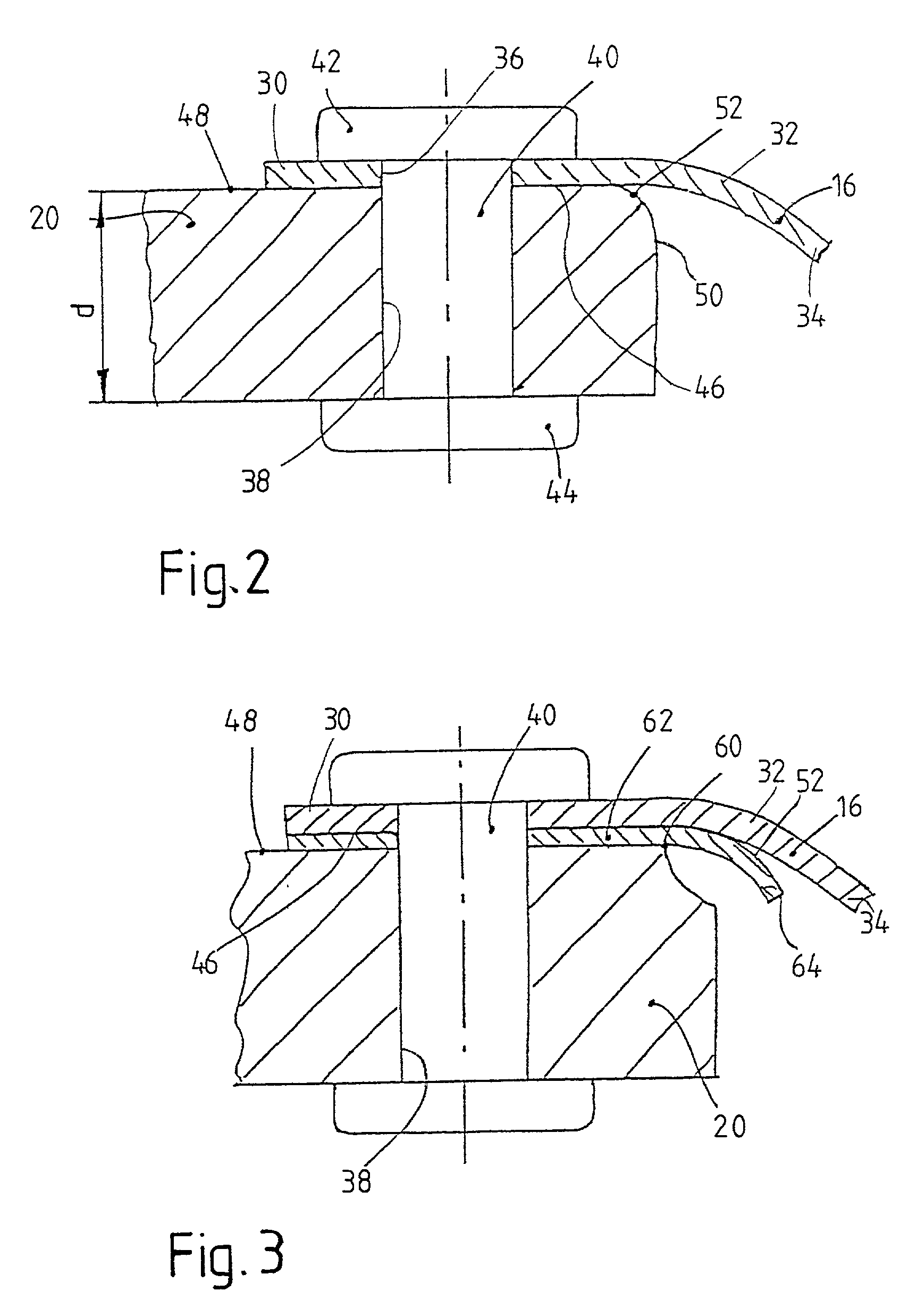
[0031] FIG. 2 shows a fastening section 20 of the pressure plate 14 in cross section along a tangent, looking in the radial direction from the outside. A first attachment area 30 of a leaf spring element 16 is attached to this fastening section 20. The essentially straight first attachment area 30 continues as a curved section 32 and then becomes another essentially straight connecting section 34, which leads to a second attachment section (not shown in the figures), which, if desired, can then be attached to the housing arrangement 12, i.e., to a fastening section 18 of same, in the same way as shown in FIG. 2. In its attachment area 30, the leaf spring element 16 has a hole 36, and a corresponding hole 38 for a clinch bolt 40 is provided in the fastening section 20. For fixation, the clinch bolt 40 has rivet heads 42, 44 at its ends. In its attachment area 30, which is connected by the rivet heads 42, 44 to the pressure plate 14, that is, to the fastening section 20 of same, the l...


PUM


Abstract

A pressure plate assembly for a friction clutch includes a housing arrangement and a pressure plate arrangement, which is held by at least one leaf spring arrangement with freedom of axial movement relative to the housing arrangement. The at least one leaf spring arrangement is fixed by a first attachment area to a first fastening area of the pressure plate arrangement and by a second attachment area to a second fastening area of the housing arrangement. The end area of the first fastening area and/or the second fastening area curves away from the minimum of one leaf spring arrangement, this end area being located in the area along which the at least one leaf spring arrangement extends.

Description

[0001] 1. Field of the Invention[0002] The present invention pertains to a friction clutch, comprising a housing arrangement and a pressure plate arrangement, which is held by at least one leaf spring arrangement with freedom of axial movement with respect to the housing arrangement. The at least one leaf spring arrangement is fixed by a first attachment area to a first fastening area on the pressure plate assembly and by a second attachment area to a second fastening area on the housing arrangement.[0003] 2. Description of the Related Art[0004] A pressure plate assembly of this type is known from, for example, DE 198 48 582. An axial view of a pressure plate assembly of this type is shown schematically in FIG. 1. This pressure plate assembly comprises a housing arrangement 12, which can be fixed to a flywheel to assemble a friction clutch. A pressure plate 14 is provided in the housing arrangement 12. A plurality of leaf spring arrangements 16, each of which can comprise, for examp...

Claims


Application Information

Patent Timeline
IPC IPC(8): F16D13/70F16D13/71
CPCF16D2013/706F16D13/71
Inventor DAU, ANDREASORLAMUNDER, ANDREASKAMMERMEIER, ALBERTBACH, HARTMUTCARLSON, CORADORFLER, MATTHIASESLY, GUNTHERFELDHAUS, REINHARDHOFFELNER, INGRIDKLEUKER, CHRISTOPHKRAUS, PAULPEINEMANN, BERNDPETERSEIM, MICHAELROLL, GERHARDTILL, RALFVOGT, SEBASTIAN
Owner ZF SACHS AG
Why Eureka
Try Eureka