Coinjection nozzle

a technology of injection nozzle and spray nozzle, which is applied in the direction of spray nozzle, combustion process, lighting and heating apparatus, etc., can solve the problem that the maintenance of the tool should be low, and achieve the effect of low maintenance and low maintenan

Inactive Publication Date: 2006-05-11
OTTO HOFSTETTER WERKZEUG UND FORMENBAU
View PDF7 Cites 16 Cited by
  • Summary
  • Abstract
  • Description
  • Claims
  • Application Information

AI Technical Summary

Benefits of technology

[0006] It is therefore the object of the present invention to provide a low maintenance coinjection nozzle for a two-component injection molding tool without the disadvantages mentioned previously. In particular, the injection molding tool should allow working at conveyor pressures of more than 1000 bar without leakages occurring between the nozzle needle and the needle guide. Furthermore, the tool should be low maintenance and should prevent an admixing of the two components in the needle tip.

Problems solved by technology

Furthermore, the tool should be low maintenance and should prevent an admixing of the two components in the needle tip.

Method used


Image

  • Coinjection nozzle
  • Coinjection nozzle
  • Coinjection nozzle

Examples


Embodiment Construction

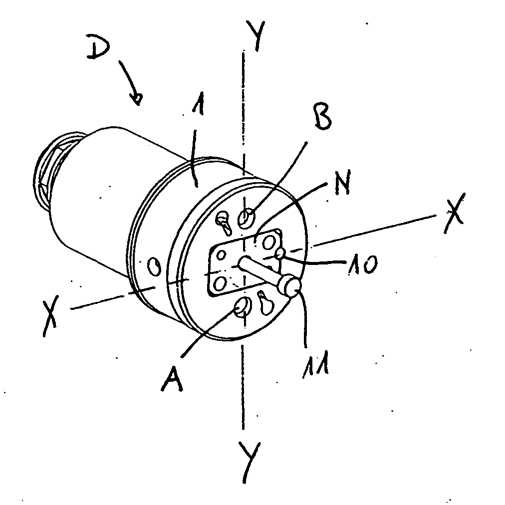
[0017]FIG. 1 shows a spatial view of an inventive coinjection nozzle D having a first supply opening for supplying an A-component and a second supply opening for supplying a B-component. In this embodiment, a needle guide base N is formed as a square plate in order to prevent the needle guide from rotating. This needle guide base N is secured to a nozzle holder 1 with the aid of a cylindrical pin 10 and serves to reliably guide the nozzle needle 11 within the nozzle D.

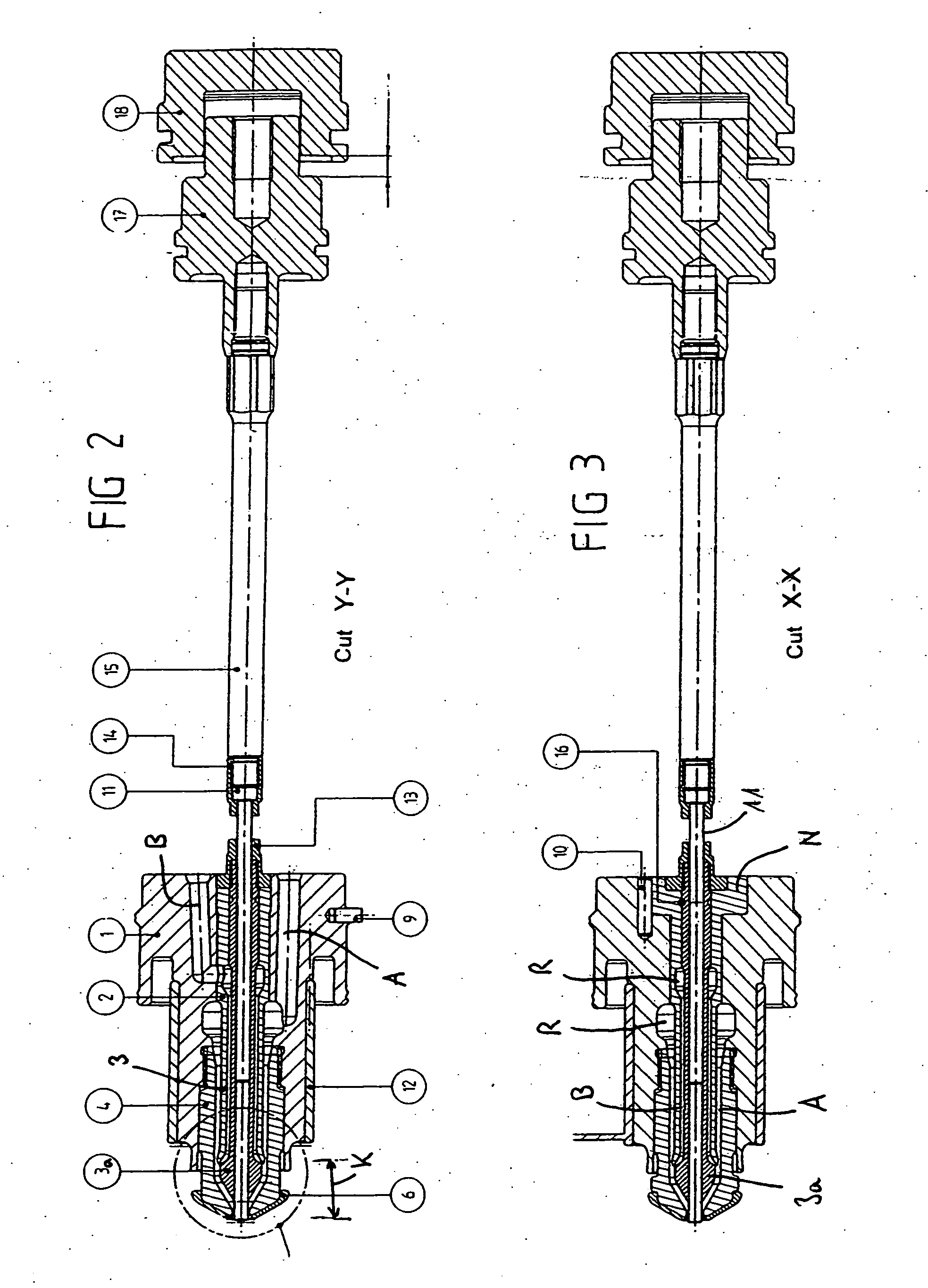
[0018] A preferred embodiment of the inventive nozzle is shown in FIG. 2. This nozzle comprises a nozzle holder 1 which is secured in the base plate by means of a cylindrical pin 9. Two supply ducts are positioned in this nozzle holder 1, a first supply duct A for an A-component and a second supply duct B for a B-component. At the discharge side of the nozzle holder 1 a nozzle tip 4 is screwed into the nozzle holder 1. A nozzle sleeve or sheath 2 is secured in the nozzle holder 1 at the base plate side. This nozzle sh...


PUM

PropertyMeasurementUnit
pressureaaaaaaaaaa
pressuresaaaaaaaaaa
pressureaaaaaaaaaa

Abstract

Disclosed is a coinjection nozzle for a two-component injection molding tool, which is used for producing parisons. The inventive nozzle comprises a nozzle holder (1) and an nozzle tip (4) that is mounted therein. A shut-off needle (11) is directed within a needle guide (3) at least in a top portion (K) of the needle tip (4). An additional nozzle sleeve (2) is disposed between the needle guide (3) and the nozzle tip (4). A first tubular delivery duct (A) extends between the nozzle sleeve (2) and the nozzle tip (4) while a second tubular delivery duct (B) extends between the nozzle sleeve (2) and the needle guide (3). The needle guide (3) is provided with a conical needle-guiding head (3a) located in the top portion (K) of the nozzle. A throat is provided in the first tubular delivery duct (A) in the area (E) of the nozzle. The needle-guiding head (3a) and the nozzle sleeve (2) are shaped in such a way that the second tubular delivery duct (B) narrows in a final area so as to form a shear edge (F).

Description

BACKGROUND OF THE INVENTION [0001] The present invention concerns a coinjection nozzle for a two-component injection molding tool according to the preamble of claim 1. [0002] Such coinjection nozzles are used in injection molding tools such as are used in the manufacture of multilayer preforms, in particular preforms suitable for blow-stretching made of PET and having a barrier layer made of Nylon®. [0003] A device with which such multilayer preforms can be manufactured is described, for example, in DE 35 19 921. Therein, a hot channel nozzle for blow-molding a multilayer body made of two components is described. This hot channel nozzle comprises two concentrically arranged heated sprue channels for supplying a first material for the first sprue channel and a second material for the second sprue channel. In the inner channel there is a pin or nozzle needle which can be moved back and forth pneumatically. This needle regulates the injection of the two components. With this nozzle, on...

Claims


Application Information

Patent Timeline
Patent Type & Authority Applications(United States)
IPC IPC(8): F02M51/00A62C31/02B05B1/14B05B1/30B29C45/16
CPCB29C45/1603B29C2045/2862B29K2105/253
Inventor HOFSTETTER, OTTOFERNANDEZ, LUIS
Owner OTTO HOFSTETTER WERKZEUG UND FORMENBAU
Why Eureka
Try Eureka