Rotor arrangement for an electric machine and a method for the manufacture of a rotor arrangement

a technology of electric machines and rotors, which is applied in the direction of dynamo-electric machines, electrical apparatus, magnetic circuit shapes/forms/construction, etc., can solve the problems of insufficient space or material volume, inability to reliably take, and inability to reduce the size of the inner ring of the rotor body, so as to improve the transfer of torque, increase the size of the shaft diameter, and the connection is more robust

Inactive Publication Date: 2006-05-11
MINEBEA CO LTD
View PDF11 Cites 30 Cited by
  • Summary
  • Abstract
  • Description
  • Claims
  • Application Information

AI Technical Summary

Benefits of technology

[0009] The invention provides a rotor arrangement for an electric machine and particularly for a brushless DC motor having an inner rotor configuration that has a substantially cylindrical rotor body which is mounted onto a shaft. According to the invention, the rotor body is divided into several identical or substantially identical rotor sections in at least one plane containing the axis of the shaft. In the preferred embodiment of the invention these rotor sections are semi-cylindrical; referred to below as “rotor halves”. The rotor sections or rotor halves are slid sideways onto the shaft and fitted together on the shaft. To create a positive fit between the shaft and the rotor body, the shaft is preferably polygonal, for example square, in at least one region in which it receives the rotor sections, so that in this region the rotor sections are connected to the sh...

Problems solved by technology

The problem arising in the manufacture of this kind of rotor back yoke is that in punching out the individual back yoke laminations there is considerable waste.
What is more, depending on the design of the rotor body, particularly in the cas...

Method used


Image

  • Rotor arrangement for an electric machine and a method for the manufacture of a rotor arrangement
  • Rotor arrangement for an electric machine and a method for the manufacture of a rotor arrangement
  • Rotor arrangement for an electric machine and a method for the manufacture of a rotor arrangement

Examples


Embodiment Construction

[0029] In the embodiments described below, the rotor body of the rotor arrangement according to the invention forms a magnetic back yoke and is built up of magnetically active (ferromagnetic) metal laminations. A person skilled in the art, however, would be aware that the basic principles of the present invention could also be applied to a non-magnetic rotor body which is not made up of individual laminations and / or made of another material. If, for example, magnets having Halbach magnetization, which do not need a magnetic back yoke, are used the rotor body can also be made from plastics, such as injection-molded plastics.

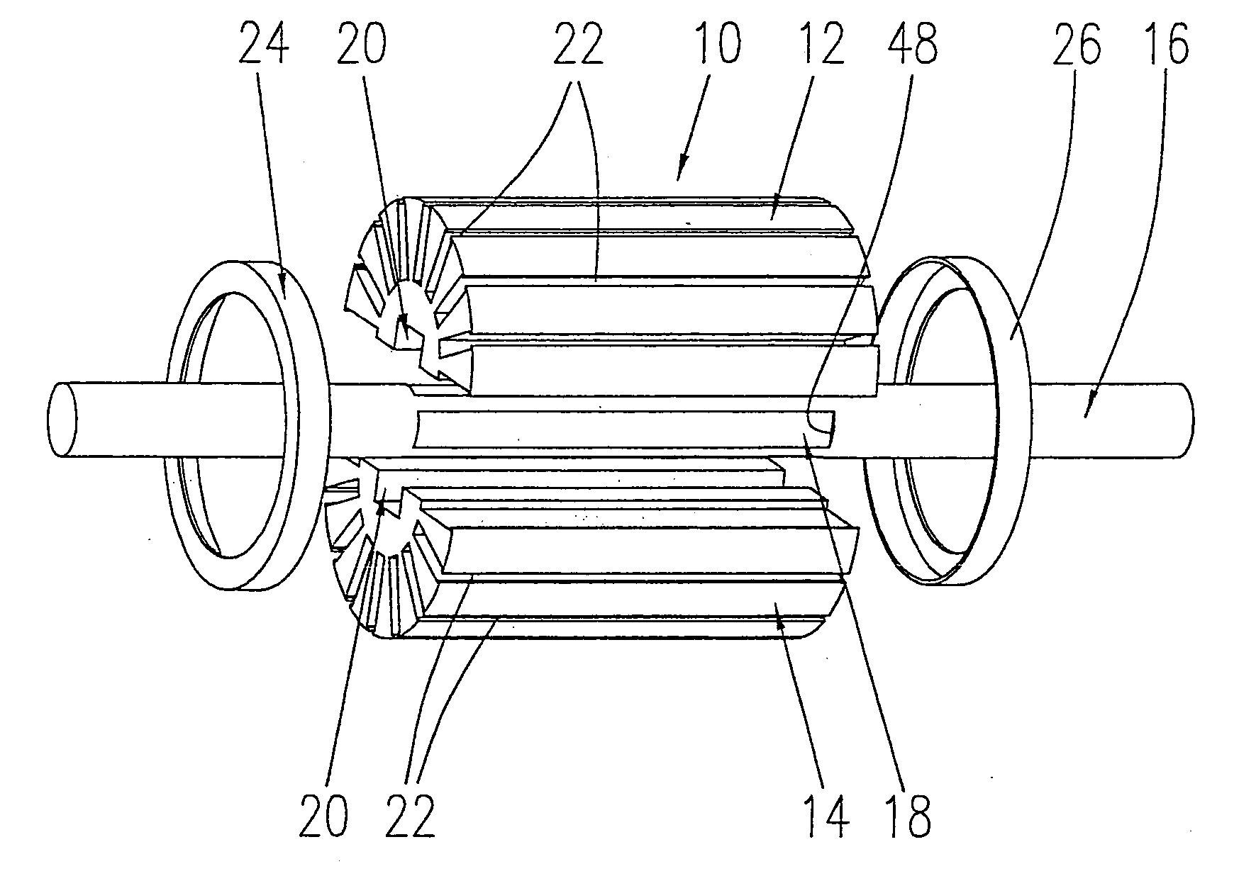
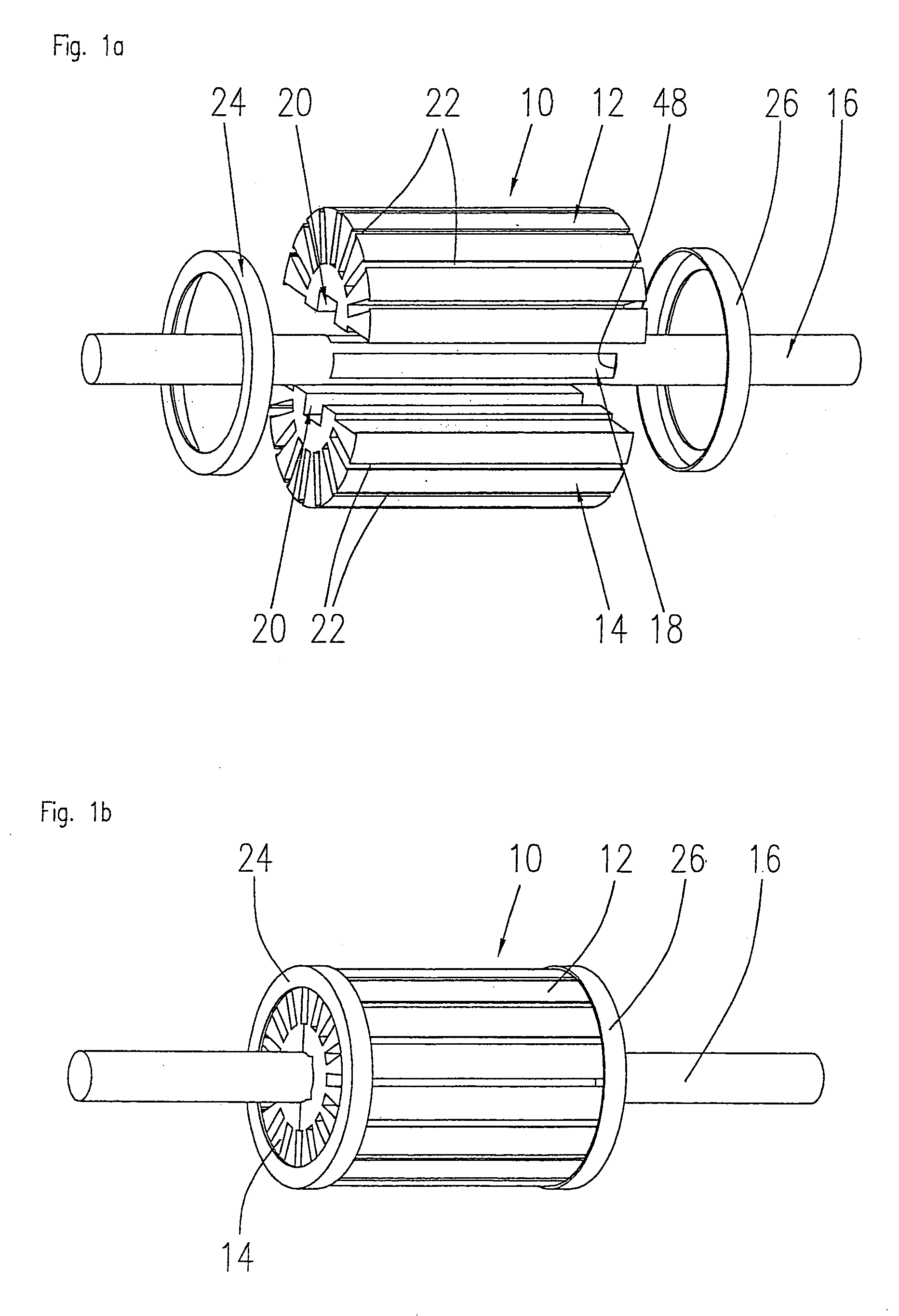
[0030]FIGS. 1a and 1b show a rotor arrangement according to a first embodiment of the invention in an exploded and an assembled view respectively. In the first and most simple embodiment of the invention a rotor body 10 is built up of two halves 12, 14 that form rotor sections and are placed against each other on a shaft 16. In the illustrated embodiment, the sha...


PUM


Abstract

A rotor arrangement for an electric machine having a substantially cylindrical rotor body and a shaft on which the rotor body is mounted, wherein the rotor body is divided into a plurality of substantially identical rotor sections in at least one plane containing the axis of the shaft, and wherein the circumference of the shaft has at least one region to receive the rotor sections and the rotor sections are connected to the shaft in a positive fit in this region.

Description

FIELD OF THE INVENTION [0001] The invention relates to a rotor arrangement for an electric machine and a method for the manufacture of a rotor arrangement. The rotor arrangement according to the invention can be employed in various types of electric machines, such as DC motors and generators. BACKGROUND OF THE INVENTION [0002] A preferred field of application for the invention is in brushless DC motors and other permanent magnet motors. In such motors, it is basically known to provide permanent magnets on the circumference of a rotor back yoke or to embed them in the back yoke. The invention can be particularly employed in electric motors and generators that are configured as inner rotor motors. Electric motors having an inner rotor configuration have a rotor back yoke that is mounted onto a shaft and one or more permanent magnets that are mounted onto the rotor back yoke or embedded in the back yoke. The motors additionally comprise a stator arrangement consisting, for example, of ...

Claims


Application Information

Patent Timeline
IPC IPC(8): H02K1/06
CPCH02K1/2773H02K15/03
Inventor HAUGER, WILLI
Owner MINEBEA CO LTD
Why Eureka
Try Eureka