Integrated GPS and SDARS antenna

Active Publication Date: 2006-05-11
XENOGENIC DEV LLC
View PDF10 Cites 54 Cited by
  • Summary
  • Abstract
  • Description
  • Claims
  • Application Information

AI Technical Summary

Problems solved by technology

Additionally, the surface area and/or material of a single or multiple plastic housings that protects each patch antenna is increased due to the implementation of multiple patch antenna units, which, if mounted exterior to a vehicle on a roof, results in a more n

Method used


Image

  • Integrated GPS and SDARS antenna
  • Integrated GPS and SDARS antenna
  • Integrated GPS and SDARS antenna

Examples


Embodiment Construction

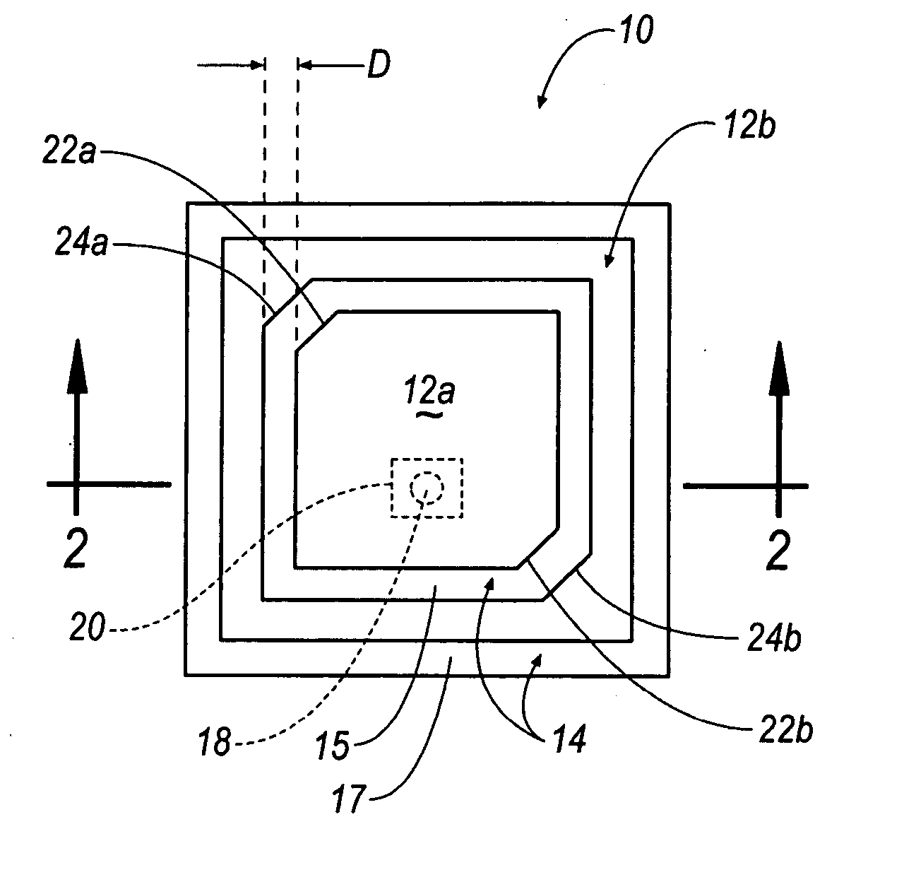
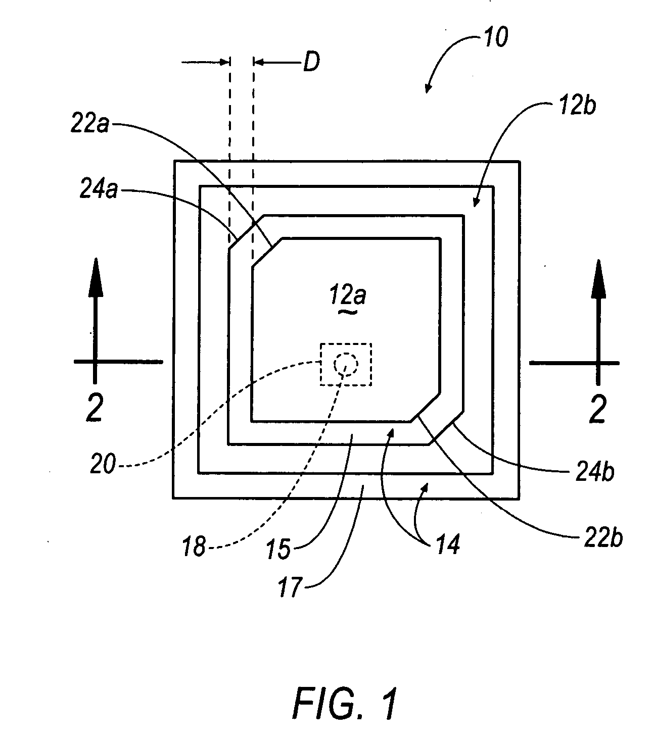
[0016] The above described disadvantages are overcome and a number of advantages are realized by an inventive integrated patch antenna, which is seen generally at 10 and 100 in FIGS. 1 and 3, respectively. According to one aspect of the invention, the integrated patch antenna 10, 100 receives global positioning system (GPS) and satellite digital audio radio system (SDARS) signals. Because both applications are independent from each other (i.e., GPS receives RHCP waves and SDARS receives LHCP waves), GPS and SDARS can be operated at the same time without interfering with each other's passive performance.

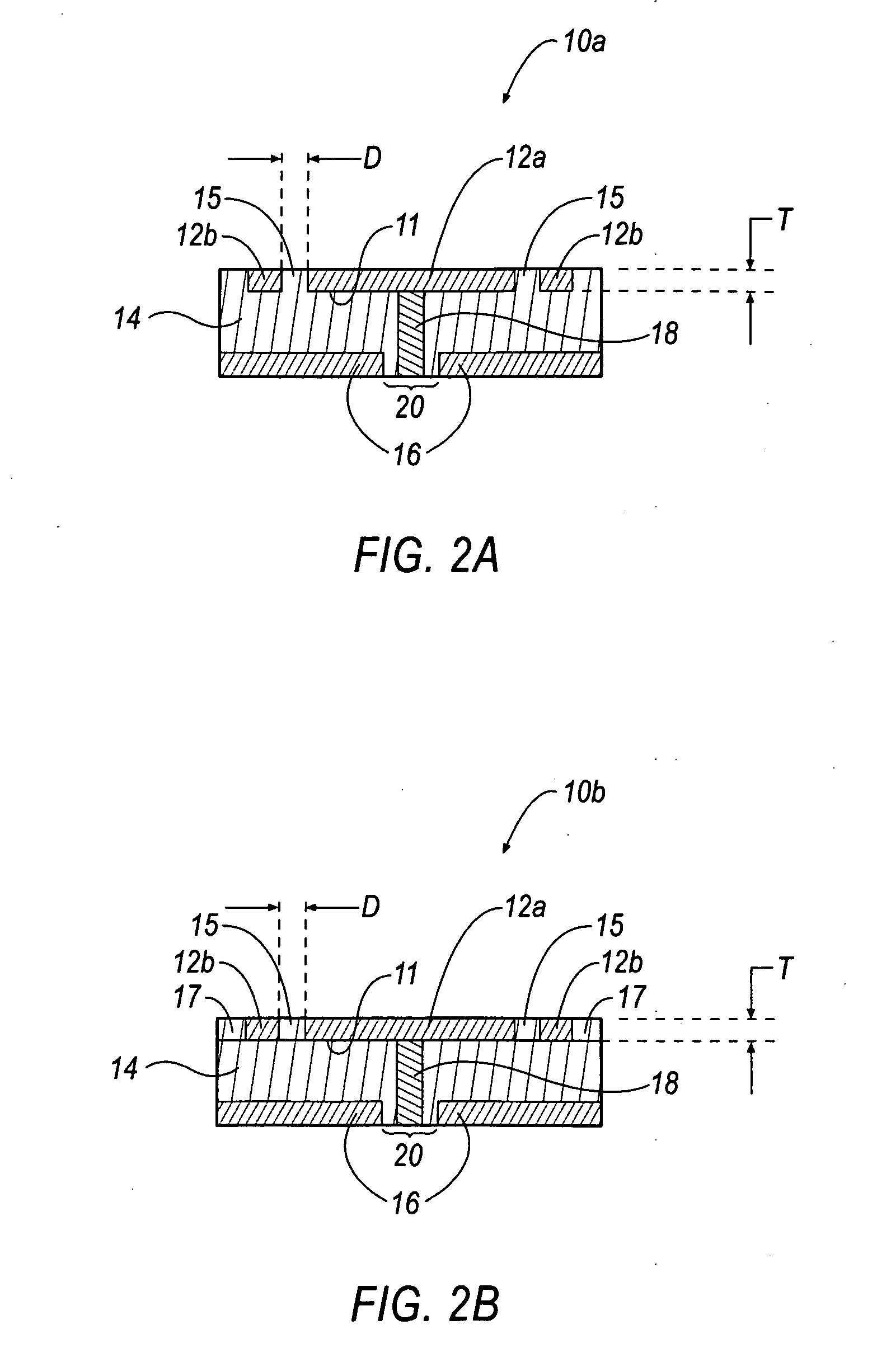
[0017] According to the first embodiment of the invention as illustrated in FIGS. 1-2B, the integrated patch antenna 10 utilizes the same-plane metallization surface to receive at least a first and second band of signals, such as GPS and SDARS. As illustrated, the same-plane metallization surface includes a first top metallization element 12a and a second top metallization element 12...


PUM


Abstract

An integrated patch antenna is disclosed. The integrated patch antenna receives at least a first and second band of signals. The integrated patch antenna includes a bottom metallization and first and second upper metallizations disposed about a dielectric material to receive the first and second signal bands. The first and second signal bands may be, for example, a satellite digital audio radio systems (SDARS) band and a global positioning system (GPS) band.

Description

TECHNICAL FIELD [0001] The present invention generally relates to patch antennas. More particularly, the invention relates to an integrated patch antenna for reception of a first and second band of signals. BACKGROUND OF THE INVENTION [0002] It is known in the art that automotive vehicles are commonly equipped with audio radios that receive and process signals relating to amplitude modulation / frequency modulation (AM / FM) antennas, satellite digital audio radio systems (SDARS) antennas, global positioning system (GPS) antennas, digital audio broadcast (DAB) antennas, dual-band personal communication systems digital / analog mobile phone service (PCS / AMPS) antennas, Remote Keyless Entry (RKE) antennas, Tire Pressure Monitoring System antennas, and other wireless systems. [0003] Currently, patch antennas are typically employed for reception and transmission of GPS [i.e. right-hand-circular-polarization (RHCP) waves] and SDARS [i.e. left-hand-circular-polarization (LHCP) waves]. Patch ant...

Claims


Application Information

Patent Timeline
IPC IPC(8): H01Q1/38H01Q5/378H01Q5/40
CPCH01Q9/0407H01Q9/0414H01Q5/40H01Q9/0428H01Q5/378H01Q9/0421
Inventor YEGIN, KORKUTMORRIS, DANIEL G.BALLY, NAZAR F.SNOEYINK, RANDALL J.LIVENGOOD, WILLIAM R.
Owner XENOGENIC DEV LLC
Why Eureka
Try Eureka