

Position-detecting system
- Summary
- Abstract
- Description
- Claims
- Application Information
AI Technical Summary
Benefits of technology
Problems solved by technology
Method used
Image

Examples
first embodiment
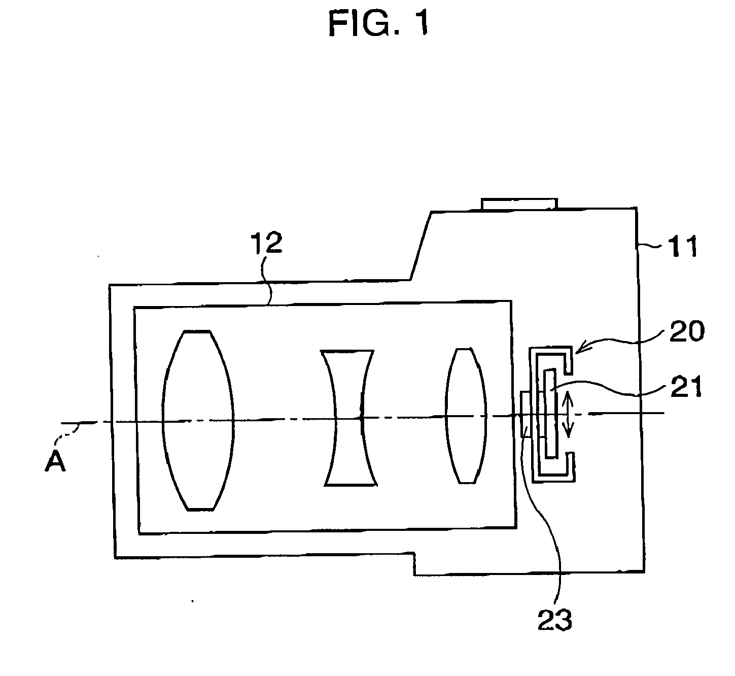
[0041]FIGS. 1-5 illustrate the present invention, where the invention is applied to a digital camera, as an example.
[0042] Referring to FIG. 1, a lens block 12 or a photographing optical system is provided inside a camera body 11. Behind the lens block 12, an anti-shake mechanism provided with an imaging device (CCD) 23, is arranged. A casing 21 of the anti-shake mechanism 20 is movable along a plane perpendicular to the optical axis “A” of the photographing optical system, thereby camera-shake induced by handshake can be compensated.
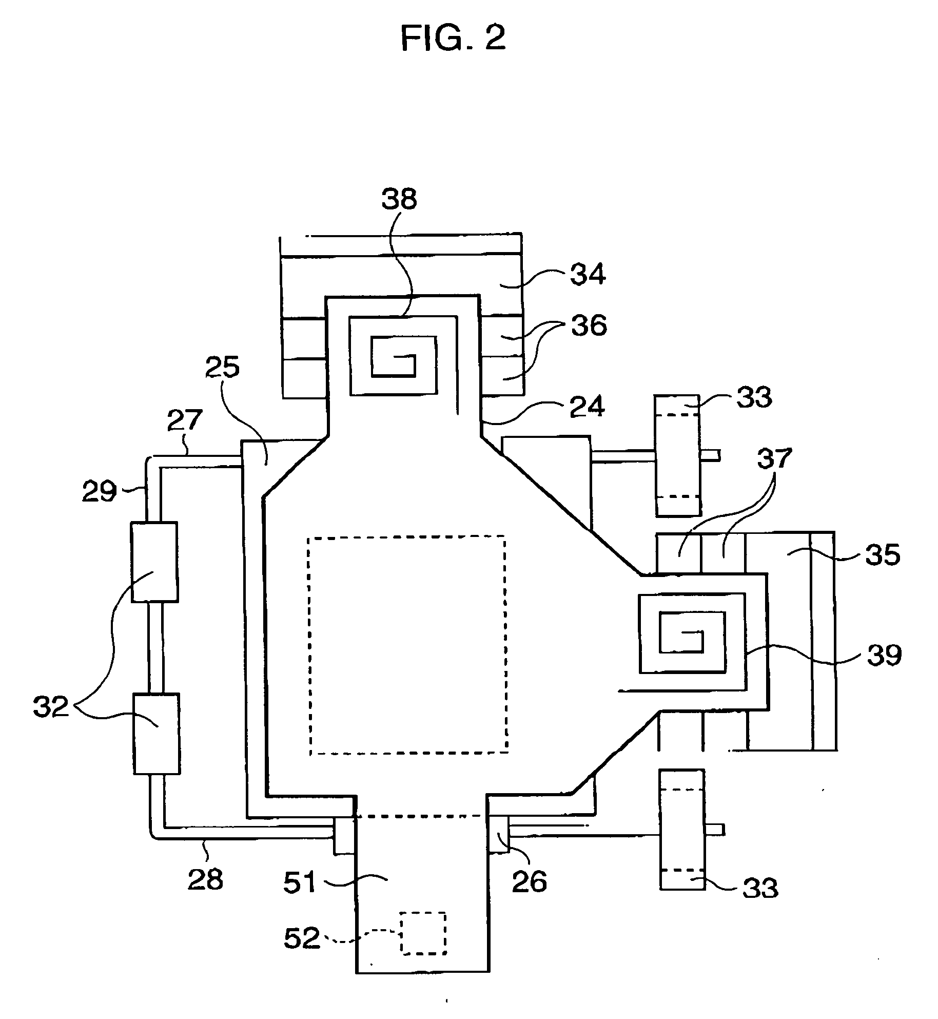
[0043] With reference to FIGS. 2 and 3, structures of the anti-shake mechanism 20 will be explained. However, anti-shake methods or camera-shake compensation methods are well known in the art, therefore, an explanation of the methods will be omitted.
[0044] A fixed member 31 is fixed to a retaining frame (not shown) provided inside the camera body. A first support member 32, second support members 33, a first yoke 34, and a second yoke 35 are provided ...
third embodiment
[0076] Inside the light source unit 121, two light emitting devices, such as LEDs 122a and 122b are mounted. In front of each LED 122a and 122b, i.e. on the position-sensing device 111 side, a spot mask 123 is disposed. The spot mask 123, is perforated with holes 123a and 123b which penetrate the mask 123, enabling spotlight from the LEDs 122a and 122b to pass. Each of the spotlights emitted through each of the LEDs 122a and 122b is made incident to the light receiving area 112 of the position-sensing device 111 and forms respective spots “a” and “b”. In the third embodiment, the LEDs 122a and 122b are alternately turned on and turned off at the same interval, as that shown in the timing chart of FIG. 12, so that the spot “a” of the LED 122a and the spot “b” of the LED 122b are alternately detected on the light receiving area 112.
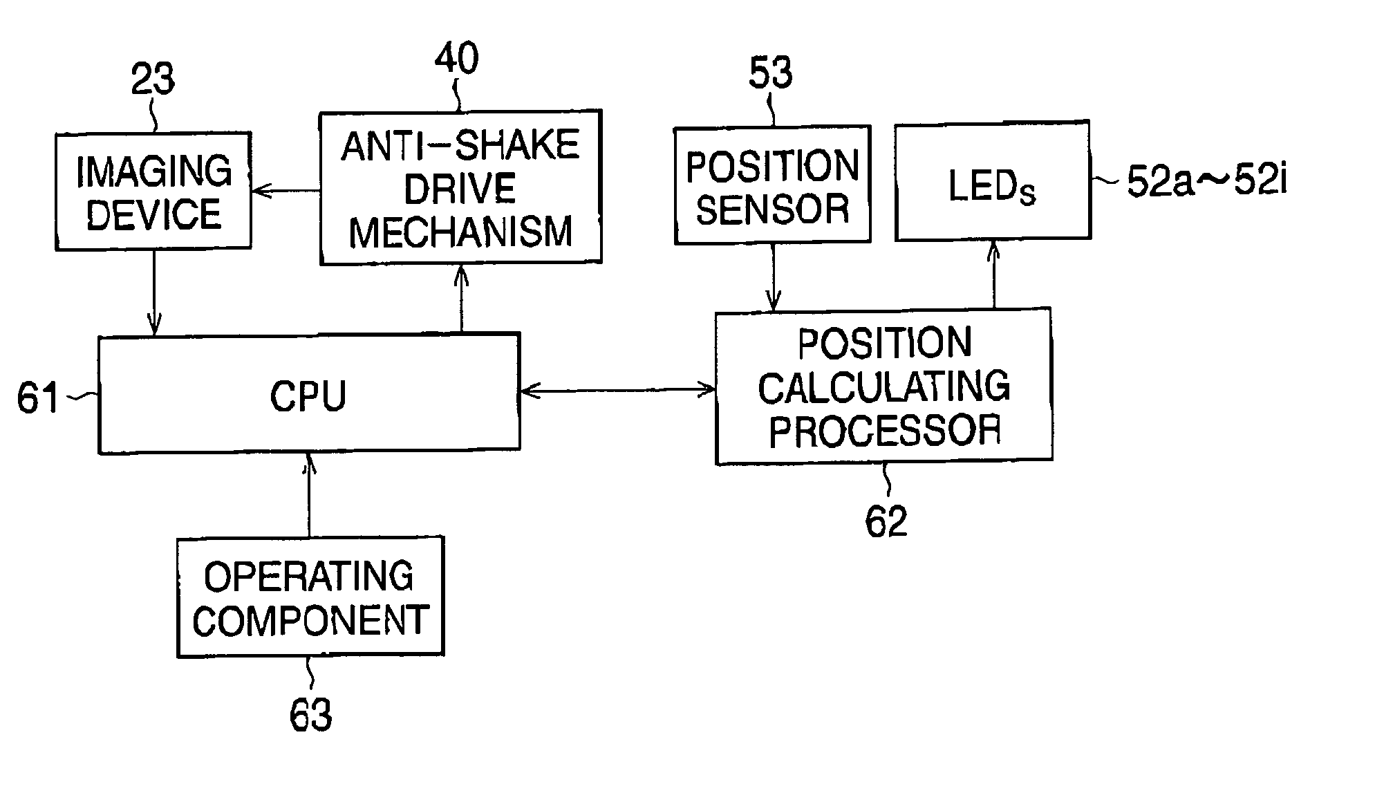
[0077]FIG. 13 is a block diagram showing an electric schematic of the position-detecting system of the third embodiment. The LEDs 122a and 122b are turned ...
PUM
 Abstract
Description
Claims
Application Information