Power feed device of inductive charging device

Active Publication Date: 2017-05-23
PANASONIC INTELLECTUAL PROPERTY MANAGEMENT CO LTD
View PDF15 Cites 0 Cited by
  • Summary
  • Abstract
  • Description
  • Claims
  • Application Information

AI Technical Summary

Benefits of technology

The patent aims to provide a power feeding device for a non-contact charging device that can reduce ripple in output, be smaller and cheaper, and minimize loss of power feed. The device uses a multiple column circuit and a smoothing capacitor to achieve these effects. Overall, the invention helps to create a more stable and efficient power feeding system.

Problems solved by technology

However, the multiple column circuits (converters) are required, and parts count of the power feeding device increases.
This increases size and cost of the power feeding device, and increases loss of power feed.

Method used


Image

  • Power feed device of inductive charging device
  • Power feed device of inductive charging device
  • Power feed device of inductive charging device

Examples


first embodiment

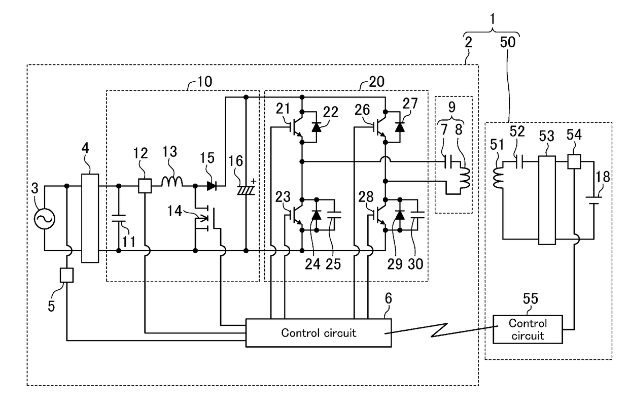
[0026]FIG. 1 is a circuit diagram of a non-contact charging device of a first embodiment.

[0027]As shown in FIG. 1, a non-contact charging device 1 includes a power feeding device 2 located at a parking lot, for example, and a power receiving device 50 mounted on an electric propulsion vehicle, for example. The power feeding device 2 includes a commercial power supply 3, a first rectifier circuit 4, a synchronizing signal generator 5, a control circuit 6 for the power feeding device 2 (hereinafter merely referred to as a “control circuit 6”), a power feeding section 9, a power factor improvement circuit 10, and an inverter circuit 20.

[0028]The power receiving device 50 includes a second inductor 51, a second resonant capacitor 52, a second rectifier circuit 53, a load (e.g., a battery) 18, a power reception detector 54, and a control circuit 55 for the power receiving device 50 (hereinafter merely referred to as a “control circuit 55”).

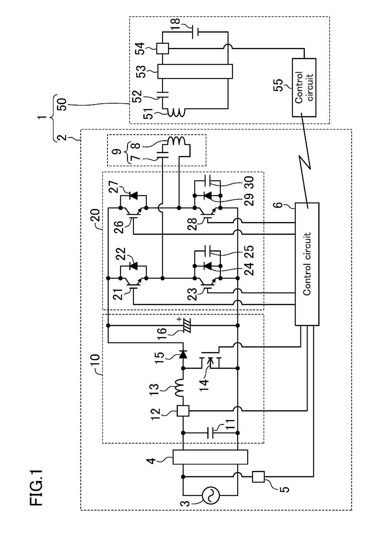
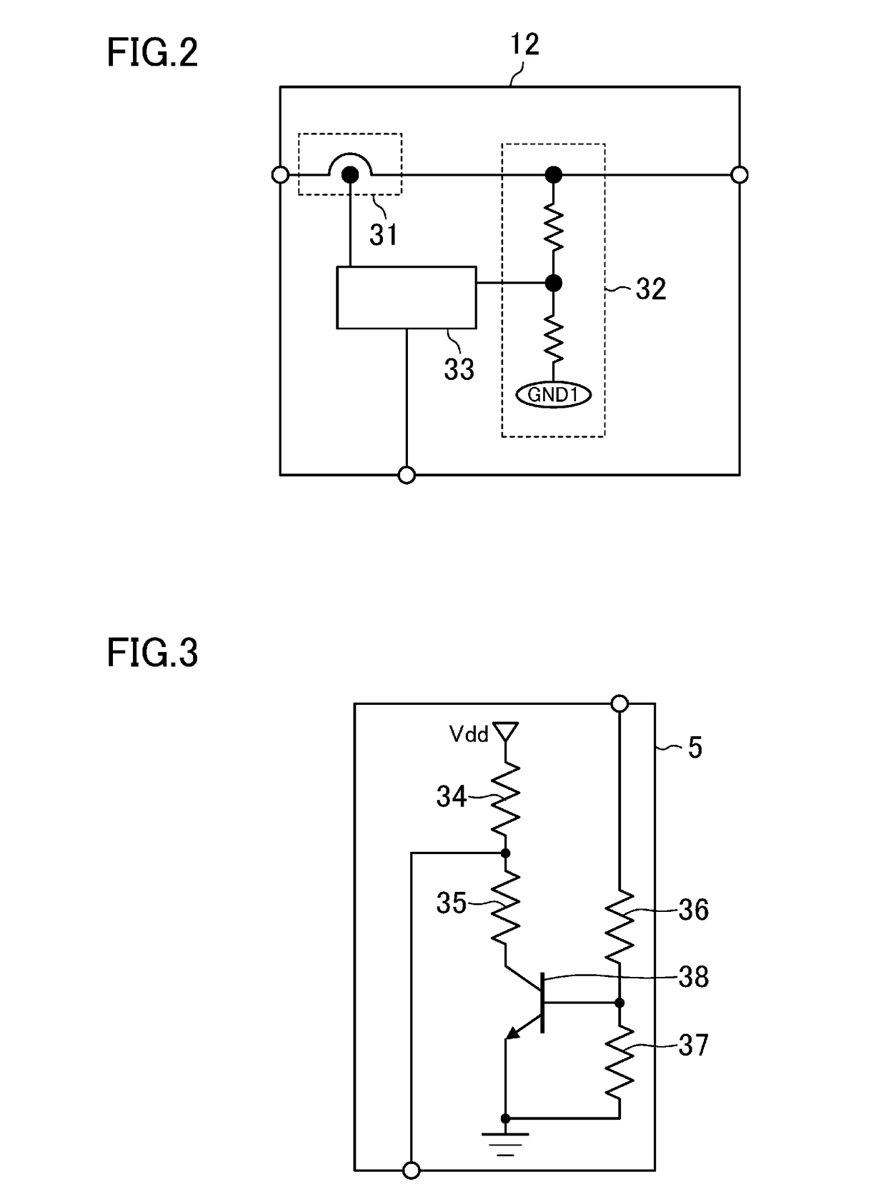
[0029]Configurations of these circuit blocks wil...


PUM


Abstract

A power feeding device of a non-contact charging device includes a power factor improvement circuit which converts an AC power supply to DC, and improves a power factor, a smoothing capacitor connected to an output end of the power factor improvement circuit, an inverter circuit which includes a plurality of switching elements, and generates an AC signal using a voltage of the smoothing capacitor as a power supply, a power feeding section which feeds power based on the AC signal to a power receiving device, and a control circuit which modulates a duty factor of each of the switching elements of the inverter circuit in synchronization with the AC power supply, wherein the control circuit controls the plurality of switching elements so that an increment of the modulated duty factor is not equal to a decrement of the modulated duty factor.

Description

CROSS-REFERENCE TO RELATED APPLICATIONS[0001]This is a continuation of International Application No. PCT / JP2013 / 001540 filed on Mar. 8, 2013, which claims priority to Japanese Patent Application No. 2012-059786 filed on Mar. 16, 2012. The entire disclosures of these applications are incorporated by reference herein.BACKGROUND[0002]The present disclosure relates to non-contact charging devices for charging secondary batteries mounted, for example, on electric propulsion vehicles (electric vehicles and hybrid electric vehicles) in a non-contact fashion.[0003]Technologies using a magnetic field, an electric field, a radio wave, etc., have been developed to achieve power transfer in a non-contact fashion. The non-contact power transfer technology does not require any wires for connecting a power feeding device and a power receiving device, and users do not have to connect the devices, and do not have to worry about leakage and an electric shock in the event of rain.[0004]In the non-cont...

Claims


Application Information

Patent Timeline
IPC IPC(8): H02M1/14H02J50/10H02J7/02H02M1/42H02J50/80H02M1/00
CPCH02M1/14H02J7/025H02J50/10H02J50/80H02M1/4208H02M1/4225H02M2001/007Y02B70/126H02J7/00034Y02B70/10H02M1/007H02J50/12
Inventor SADAKATA, HIDEKIFUJITA, ATSUSHIKASHIMOTO, TAKASHIBESSYO, DAISUKE
Owner PANASONIC INTELLECTUAL PROPERTY MANAGEMENT CO LTD
Why Eureka
Try Eureka