Wireless LAN device and controlling method thereof

a wireless lan and control method technology, applied in the direction of frequency-division multiplex, transmission monitoring, instruments, etc., can solve the problems of increasing the size and the access point cannot communicate for a long period, and the communication failure of the access point cannot be at least for a minute, so as to suppress the increase in the size and cost of the access point, and avoid the occurrence of communication failures. , the effect of increasing the size and cos

Active Publication Date: 2012-08-23
BUFFALO CORP LTD
View PDF5 Cites 108 Cited by
  • Summary
  • Abstract
  • Description
  • Claims
  • Application Information

AI Technical Summary

Benefits of technology

[0012]One conceivable way to avoid such a problem is to add a circuit dedicated to monitoring the radar waves to the access point so as to monitor radar waves in the other frequency channel by using the circuit dedicated to monitoring during communication in the original frequency channel included in the DFS band. However, this method leads to increases in the size and costs of the access point by with the circuit dedicated to monitoring added.
[0013]It is therefore an object of this disclosure to provide a wireless LAN device which is capable of avoiding occurrence of a communication failure over a long period while suppressing increases in the size and costs and to provide a controlling method thereof.

Problems solved by technology

As a consequence, the access point cannot resume the communication at least for one minute.
Hence the access point cannot communicate for a long period.
However, this method leads to increases in the size and costs of the access point by with the circuit dedicated to monitoring added.

Method used


Image

  • Wireless LAN device and controlling method thereof
  • Wireless LAN device and controlling method thereof
  • Wireless LAN device and controlling method thereof

Examples


embodiment

(4) Effect of Embodiment

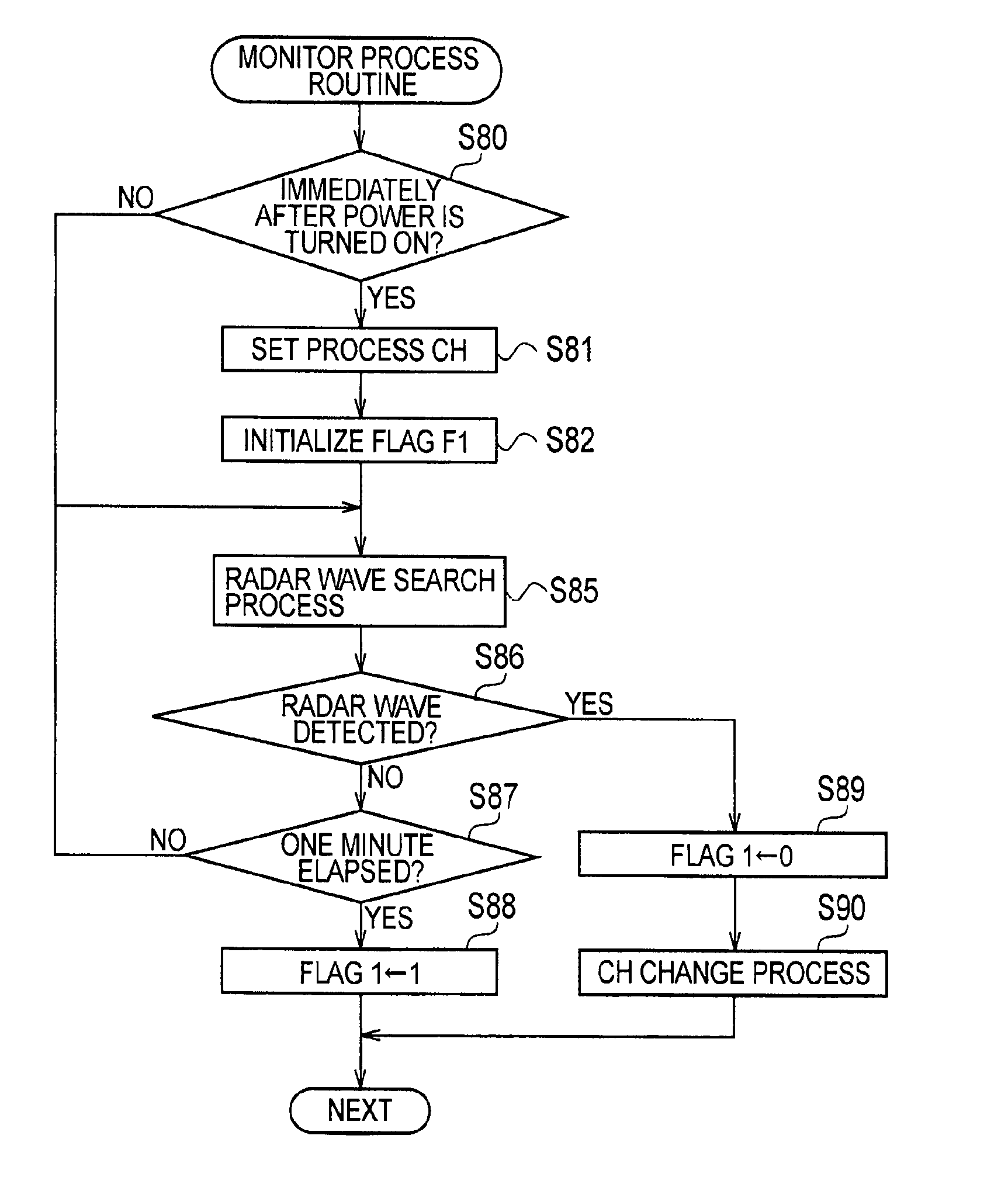
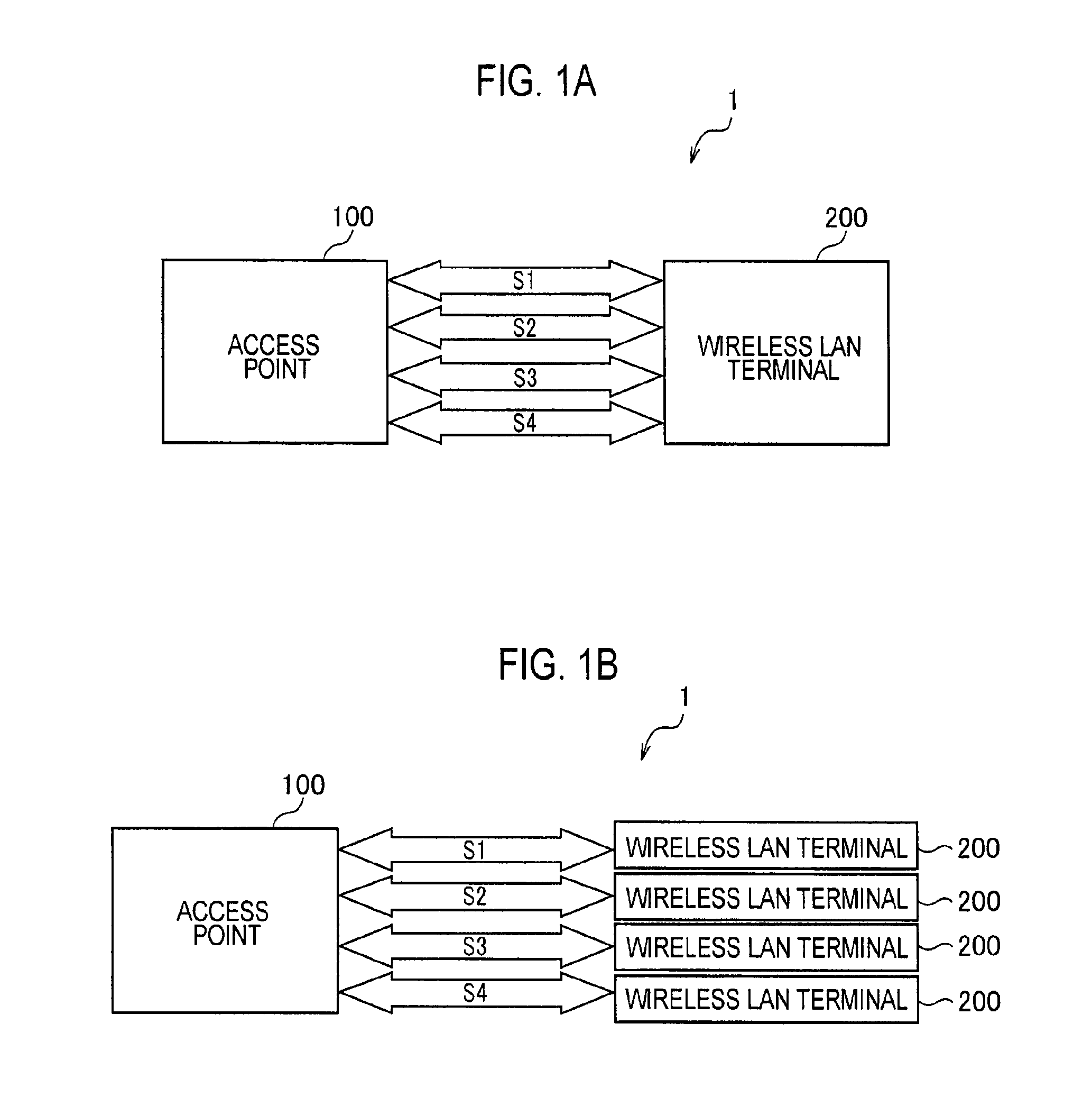
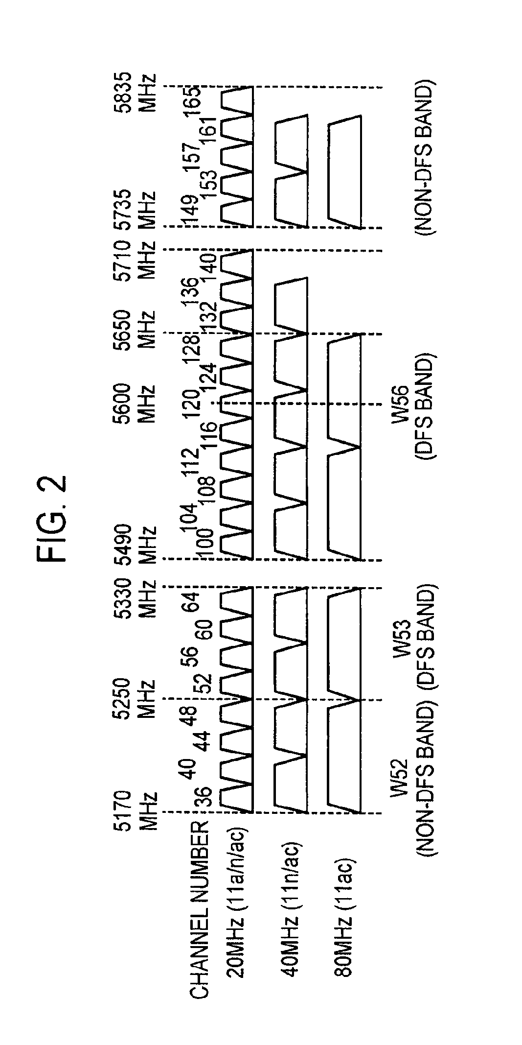
[0110]As described above, when the frequency channel in use for the wireless communication is the specific frequency channel shared by the radar and the wireless LAN system (i.e. the frequency channel included in the DFS band), the access point 100 of this embodiment monitors the radar waves on the frequency channel other than the frequency channel in use by using the transceiver circuit 170 among the transceiver circuits 140, 150, 160, and 170 used for the wireless communication in accordance with the MIMO scheme.

[0111]In this way, it is possible to monitor the radar waves on the different frequency channel while wirelessly communicating on the frequency channel included in the DFS band. Accordingly, even when the radar wave is detected in the frequency channel in use, it is possible to avoid occurrence of a communication failure of the access point 100 over a long period.

[0112]Moreover, the radar wave monitoring is carried out with the transceiver circuit 1...


PUM


Abstract

A wireless LAN device for wirelessly communicating using a specific frequency channel shared by a radar and a wireless LAN system. The wireless LAN device includes a plurality of antennas; a wireless communication unit including a plurality of transceiver circuits respectively provided for each of the plurality of antennas; and a controller that controls the wireless communication unit. The wireless communication unit wirelessly communicates in accordance with a multiple input multiple output (MIMO) scheme by the plurality of transceiver circuits, and the controller controls the wireless communication unit to execute radar wave monitoring on a frequency channel different from a frequency channel in use for wireless communication using one of the plurality of transceiver circuits when the frequency channel in use for the wireless communication is the specific frequency channel.

Description

CROSS REFERENCE TO RELATED APPLICATION[0001]This application is based upon and claims the benefit of priority from Japanese Patent Application No. 2010-269451 filed on Dec. 2, 2010; all the contents of which are incorporated herein by reference.BACKGROUND OF THE DISCLOSURE[0002]1. Field of the Disclosure This disclosure relates to a wireless LAN device for wirelessly communicating in accordance with a multiple input multiple output (MIMO) scheme in a wireless LAN system and to a controlling method thereof.[0003]2. Description of the Related Art[0004]In order to utilize available frequency band efficiently, wireless LAN systems in recent years employ a multiple input multiple output (MIMO) scheme in which a transmitter simultaneously transmits plural streams (data series) in the same frequency band through plural antennas, a receiver also receives the streams through plural antennas and then splits the streams into individual streams. This MIMO scheme can improve frequency usage effi...

Claims


Application Information

Patent Timeline
Patent Type & Authority Applications(United States)
IPC IPC(8): H04W24/00H04W84/12H04W72/02
CPCH04B7/04H04W16/14H04W72/082H04W84/12H04B17/382H04K3/226H04K3/822H04K2203/18H04L43/50H04W72/541
Inventor MATSUURA, NAGAHIRO
Owner BUFFALO CORP LTD
Why Eureka
Try Eureka