Belt drive assembly for driving accessory parts of an internal combustion engine, drive belt and pulleys suited to be used in said assembly

a technology of accessory parts and belts, which is applied in the direction of driving belts, v-belts, portable lifting, etc., can solve the problems of slipping between belts, inability to increase beyond certain limits, undesirable noise, etc., and achieves the effect of simple and economical solution and effective operation

Inactive Publication Date: 2006-05-11
DAYCO EURO
View PDF21 Cites 39 Cited by
  • Summary
  • Abstract
  • Description
  • Claims
  • Application Information

AI Technical Summary

Benefits of technology

[0010] The aim of the present invention is to provide a belt drive, particularly for driving accessory parts of an internal combustion engine in a motor vehicle comprising a reversible electric machine, which allows the effective, simple and economic solution of the disadvantages described above.

Problems solved by technology

In particular, tests carried out have revealed that, at starting, there may be slipping between the belt and the pulley of the starter / generator, which in this case has a drive function.
The problem occurs mainly due to the high torque to be transmitted and due to the fact that the arc of winding the belt onto said pulley cannot be increased beyond certain limits for reasons of bulk and the layout of the drive.
Besides causing undesirable noises and premature wear of the belt, slipping between the belt and the pulley of the starter / generator can even prevent the starting of the internal combustion engine.
It is therefore a problem that can seriously threaten the reliability of the motor vehicle.
This belt drive is therefore unsuitable to drive accessory parts of an internal combustion engine, particularly in the case where a reversible electric machine is used, in which the high torques to be transmitted require the use of a poly-V type belt.

Method used


Image

  • Belt drive assembly for driving accessory parts of an internal combustion engine, drive belt and pulleys suited to be used in said assembly
  • Belt drive assembly for driving accessory parts of an internal combustion engine, drive belt and pulleys suited to be used in said assembly
  • Belt drive assembly for driving accessory parts of an internal combustion engine, drive belt and pulleys suited to be used in said assembly

Examples


Embodiment Construction

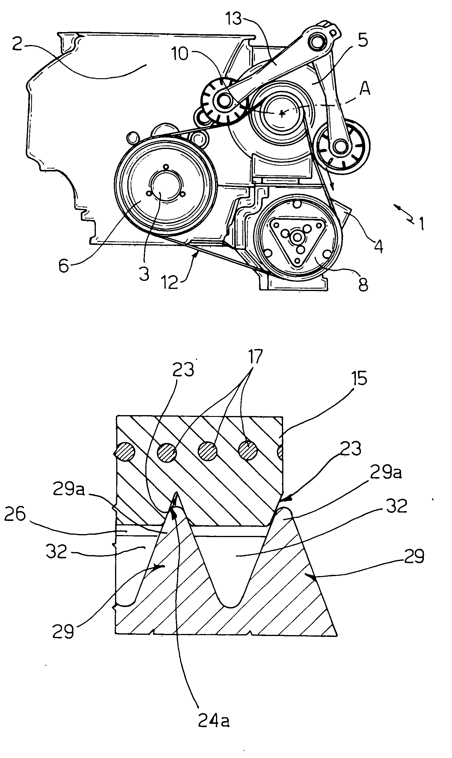
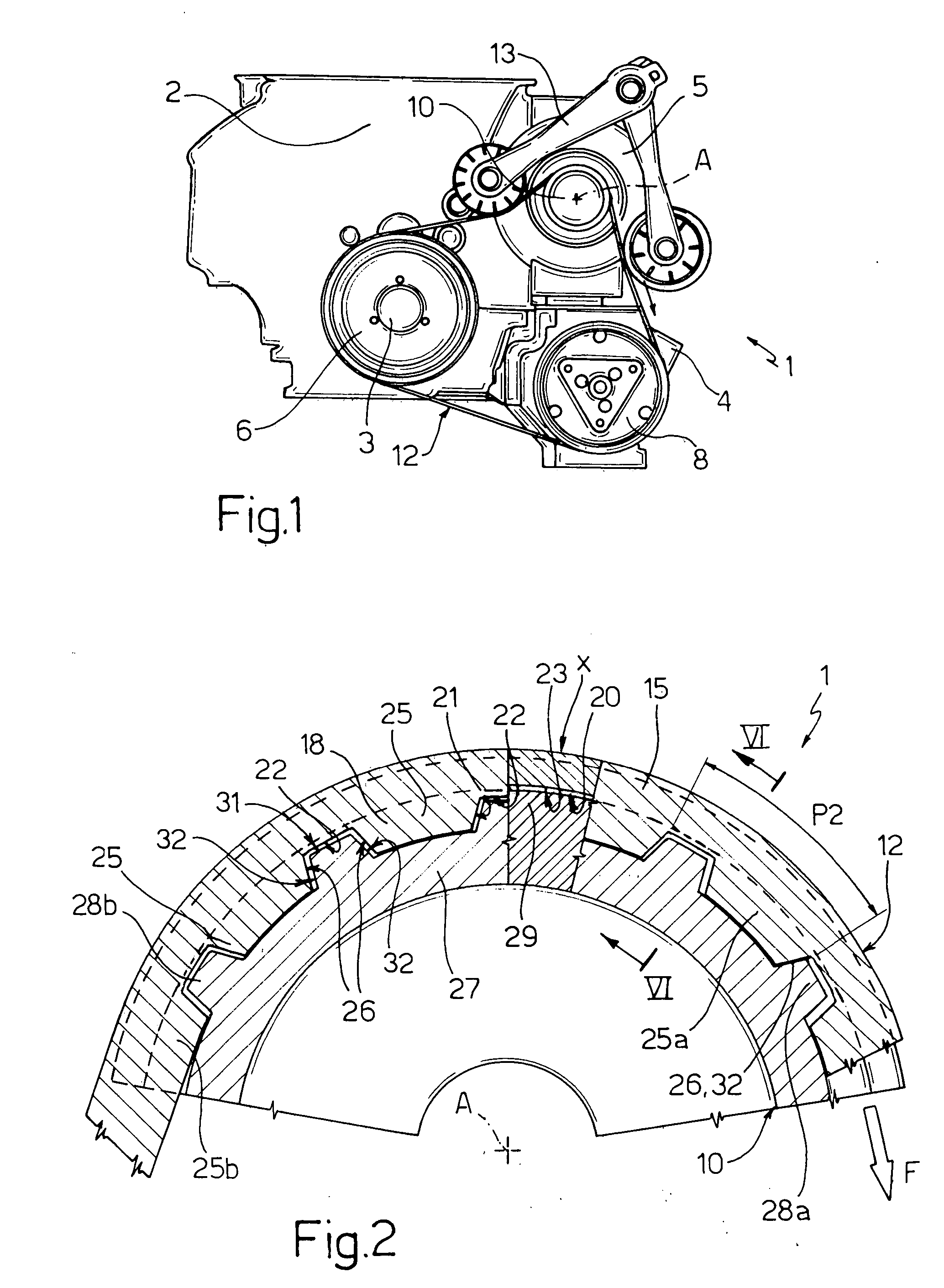
[0019] In FIG. 1, the reference 1 indicates the in its entirety a belt drive assembly for a motor vehicle, suitable to transmit movement between an internal combustion engine 2 and a plurality of auxiliary parts. These auxiliary parts comprise, in particular, a compressor 4 of an air conditioning system and an electric machine 5 of a reversible type or starter / generator, which is able to act both as a generator, when it is activated by the engine 2 in normal running conditions to charge the vehicle's electric energy accumulators (not illustrated), and as a starter, that is as an electric motor to turn over the engine 3 and make it start.

[0020] The assembly 1 comprises a pulley 6 keyed onto the engine shaft 3 of the engine 2, a pulley 8 keyed onto the drive shaft of the compressor 4, a pulley 10 keyed onto the shaft of the starter / generator 5, and a transmission belt 12, which is wound onto the pulleys 6, 8, 10 to transmit movement between the above-mentioned shafts and is subject t...


PUM


Abstract

Belt drive assembly for driving accessory parts of an internal combustion engine comprising a reversible electric machine, comprising a belt with a plurality of longitudinal ribs alternating with grooves and with a plurality of cavities spaced at equal distances from each other longitudinally and obtained transversely with respect to the ribs in such a way as to interrupt them; the pulley comprises a plurality of ribs suited to engage the grooves of the belt and a plurality of teeth transverse with respect to the ribs, spaced at equal distances from each other on the circumference and suited to engage the respective cavities of the belt. The cavities of the belt have a depth at the most equal to the height of the ribs of the belt itself, and the ribs of the pulley have a radial height larger than the teeth, so as to cooperate with the belt continuously along the whole winding arc.

Description

CROSS-REFERENCE TO RELATED APPLICATION [0001] This application claims the priority of European Patent Application No. 04425806.9 filed Oct. 28, 2004, the subject matter of which is incorporated herein by reference. BACKGROUND OF THE INVENTION [0002] The present invention concerns a belt drive, particularly for driving accessory parts of an internal combustion engine, of the type that uses a belt with multiple poly-V grooves. [0003] The present invention has a preferred application in the transmission of movement between the internal combustion engine of a motor vehicle and a plurality of accessories of the engine comprising a reversible electric machine. [0004] In the internal combustion engines of motor vehicles, to avoid installing a separate generator and starting motor, it is common practice to provide a single electric machine of a reversible type, commonly known as a starter / generator, which is able to act both as a generator, when it is activated by the internal combustion en...

Claims


Application Information

Patent Timeline
Patent Type & Authority Applications(United States)
IPC IPC(8): F16H55/50F16G5/00F16H7/12
CPCF16G1/28F16G5/20F16H7/023F16H55/171F16H55/49F16H2007/0874
Inventor DI GIACOMO, TOMMASOLEMBERGER, HEINZ
Owner DAYCO EURO
Why Eureka
Try Eureka