Tool assembly for surgical stapling device

a tool assembly and surgical staple technology, applied in the direction of surgical staples, paper/cardboard containers, surgical forceps, etc., can solve the problems of first closure and pivot points which are not particularly suited for grasping tissue, so as to improve the ability to grasp and manipulate tissu

Active Publication Date: 2006-05-11
TYCO HEALTHCARE GRP LP
View PDF99 Cites 54 Cited by
  • Summary
  • Abstract
  • Description
  • Claims
  • Application Information

AI Technical Summary

Benefits of technology

[0010] In accordance with the present disclosure, a tool assembly having a pair of jaws is disclosed. Each of the jaws has a proximal end and a distal end and the first jaw is movable in relation to the second jaw between a spaced position and an approximated position. First and second cam followers are supported on the first jaw. An approximation member is movable in relation to the first jaw and includes at least one cam surface positioned to engage the first and second cam followers. The approximation member is movable in relation to the first jaw to move the at least one cam surface in relation to the first and second cam followers to effect movement of the first and second jaws from the spaced position to the approximated position. The at least one cam channel is configured to approximate the distal ends of the first and second jaws prior to approximation of the proximal ends of the first and second jaws. By approximating the distal ends of the first and second jaws first, tissue positioned between the jaws is not pushed forward within the jaws during closure of the jaws. Further, the jaws are better able to grip and manipulate tissue using the distal ends of the jaws.

Problems solved by technology

One problem associated with conventional staplers and tool assemblies is that as the anvil and cartridge pivot in relation to each other, closure occurs first at the proximal end of the jaws and thereafter at the distal end of the jaws.
Conventional staplers having an anvil or cartridge mounted to a fixed pivot point which are pivotable to a closed position are not particularly suited for grasping tissue because only a limited clamping force is produced at the distal end of the jaws.

Method used


Image

  • Tool assembly for surgical stapling device
  • Tool assembly for surgical stapling device
  • Tool assembly for surgical stapling device

Examples


Embodiment Construction

[0027] Preferred embodiments of the presently disclosed tool assembly for a stapling device will now be described in detail with reference to the drawings in which like reference numerals designate identical or corresponding elements in each of the several views.

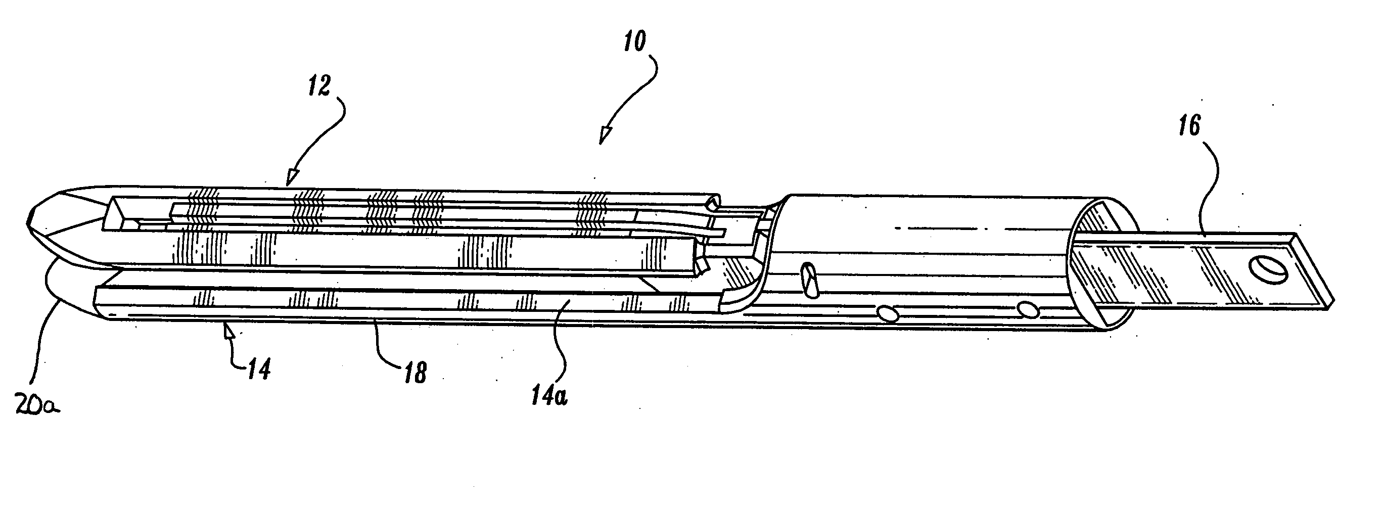
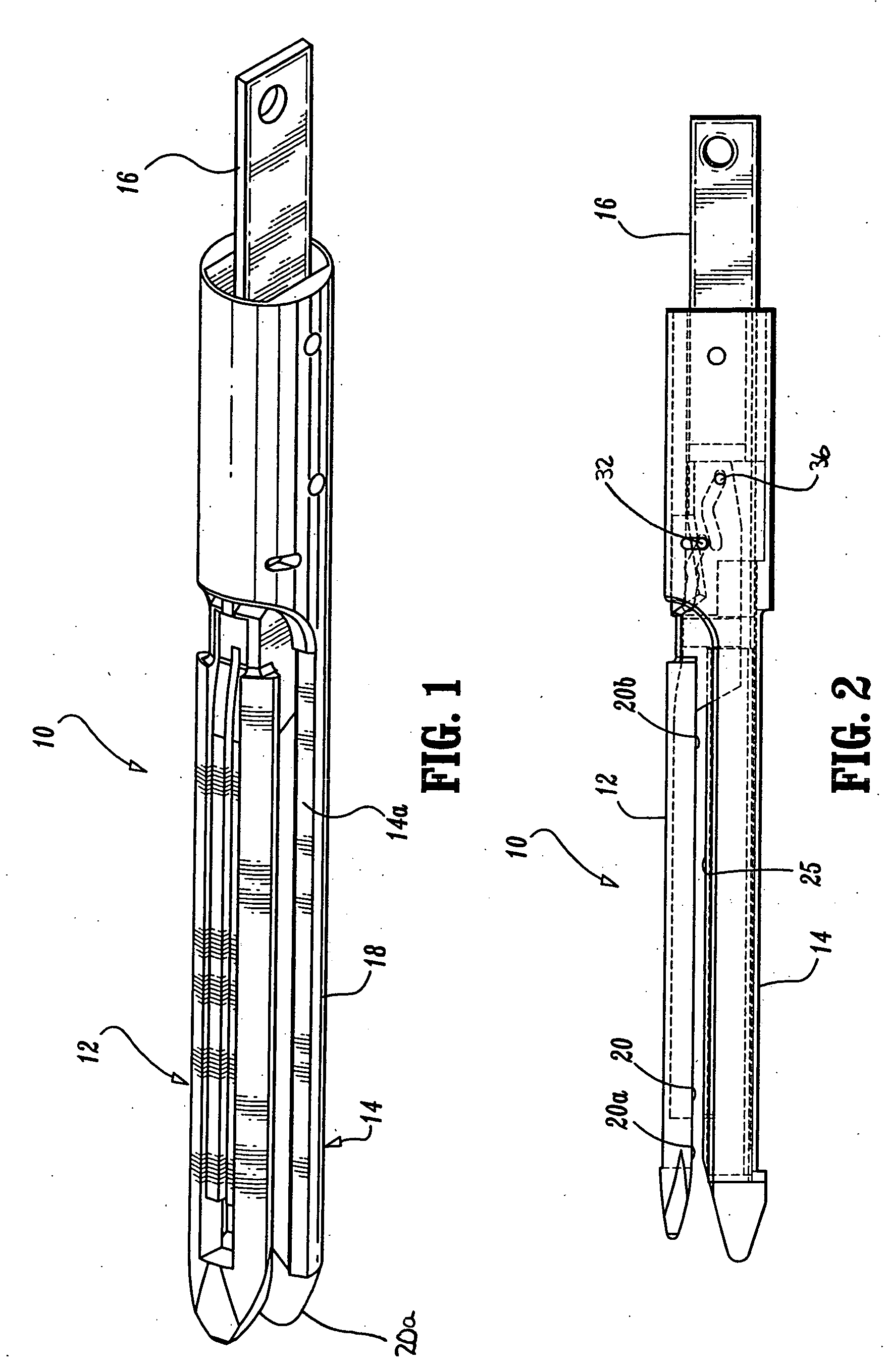
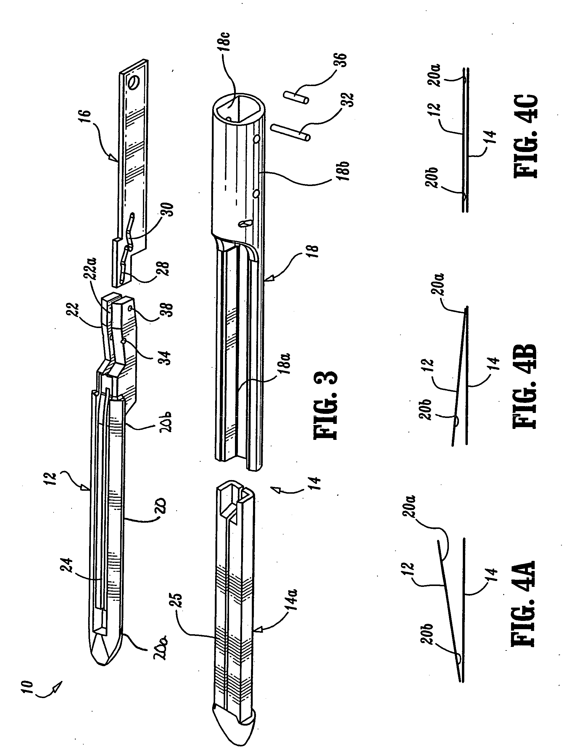
[0028]FIGS. 1-3 illustrate one preferred embodiment of the presently disclosed tool assembly shown generally as 10 for use with a surgical stapling device. Tool assembly 10 includes a pair of jaws including an anvil 12 and a cartridge assembly 14 and an approximation member 16. Cartridge assembly 14 includes a support channel 18 for receiving a staple cartridge 14a. Support channel 18 includes distal open channel portion 18a and a proximal portion 18b defining a truncated cylinder 18c. Although not shown in detail, staple cartridge 14a houses a plurality of staples and can include conventional pushers (not shown) for translating movement of a staple drive assembly that typically includes a sled (e.g., 131 in FIG. 6) to move...


PUM

PropertyMeasurementUnit
angleaaaaaaaaaa
flexibleaaaaaaaaaa
areaaaaaaaaaaa

Abstract

A tool assembly having a pair of jaws is disclosed. Each of the jaws has a proximal end and a distal end and the first jaw is movable in relation to the second jaw between a spaced position and an approximated position. First and second cam followers are supported on the first jaw. An approximation member is movable in relation to the first jaw and includes at least one cam surface positioned to engage the first and second cam followers. The approximation member is movable in relation to the first jaw to move the at least one cam surface in relation to the first and second cam followers to effect movement of the first and second jaws from the spaced position to the approximated position. The at least one cam channel is configured to approximate the distal ends of the first and second jaws prior to approximation of the proximal ends of the first and second jaws. In another preferred embodiment, the tool assembly includes an articulation and firing actuator. The articulation and firing actuator includes a flexible band having a first end portion extending at least partially through the body portion and through the cartridge assembly, a central portion extending from the first end portion operably associated with the dynamic clamping member and a second end portion extending from the central portion through the cartridge assembly and at least partially through the body portion to a position adjacent the first end. The articulation and firing actuator is operably associated with the tool assembly such that movement of either the first end portion or the second end portion of the flexible band proximally and independently of the other end portion effects pivoting of the tool assembly in relation to the body portion, and movement of both the first and second end portions of the flexible band simultaneously effects movement of the dynamic clamping member to eject the staples from the cartridge assembly.

Description

[0001] This application claims priority from U.S. Provisional application Ser. No. 60 / 416,056, entitled Tool Assembly For Surgical Stapling Device and filed Oct. 4, 2003, the entire contents of which are incorporated herein by reference.BACKGROUND [0002] 1. Technical Field [0003] The present disclosure relates generally to a surgical tool assembly for manipulating and / or applying fasteners to tissue. More specifically, the present disclosure relates to a surgical tool assembly having a pair of jaws including a unique approximation mechanism to facilitate improved clamping and manipulation of tissue. [0004] 2. Background of Related Art [0005] Surgical staplers and tool assemblies for clamping tissue between opposed jaw structure of a tool assembly and thereafter fastening the clamped tissue are well known in the art. These devices may include a knife for incising the fastened tissue. Such staplers having laparoscopic or endoscopic configurations are also well known in the art. Exampl...

Claims


Application Information

Patent Timeline
Patent Type & Authority Applications(United States)
IPC IPC(8): A61B17/10A61B17/072A61B17/125A61B17/28
CPCA61B17/07207A61B2017/00367A61B2017/07214A61B2017/07271A61B2017/07285A61B2017/2927A61B2017/2931A61B2017/2934A61B2017/2936A61B2017/2944
Inventor VIOLA, FRANKJ
Owner TYCO HEALTHCARE GRP LP
Why Eureka
Try Eureka