Method and system for imaging using a filter for time-of-flight pet

a technology of time-of-flight pet and filter, applied in the field of positron emission tomography (pet) systems, can solve the problems of blurred and distorted images obtained through bp operation, uncertainty in the measurement of tof, and inexact measurement of to

Inactive Publication Date: 2006-05-18
GENERAL ELECTRIC CO
View PDF1 Cites 28 Cited by
  • Summary
  • Abstract
  • Description
  • Claims
  • Application Information

AI Technical Summary

Problems solved by technology

The image obtained through BP operation is, however, blurred and distorted.
In practical TOF-PET systems, the measurement of TOF is not exact and there is some uncertainty in its measurement.
This uncertainty in the measurement of TOF translates to an uncertainty in the localization of the annihilation events.
In particular, a simple ramp filter, similar to the one used in conventional FBP, over-compensates for high frequencies and may produce over and / or under-shoots.

Method used


Image

  • Method and system for imaging using a filter for time-of-flight pet
  • Method and system for imaging using a filter for time-of-flight pet
  • Method and system for imaging using a filter for time-of-flight pet

Examples


Embodiment Construction

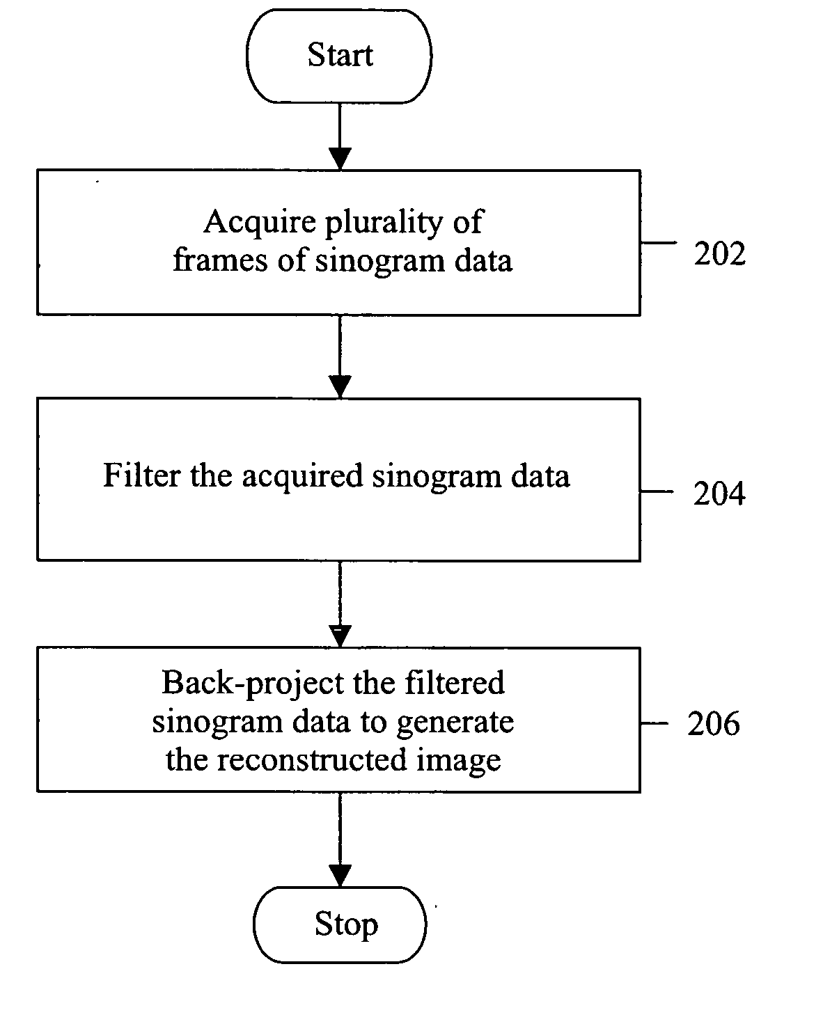
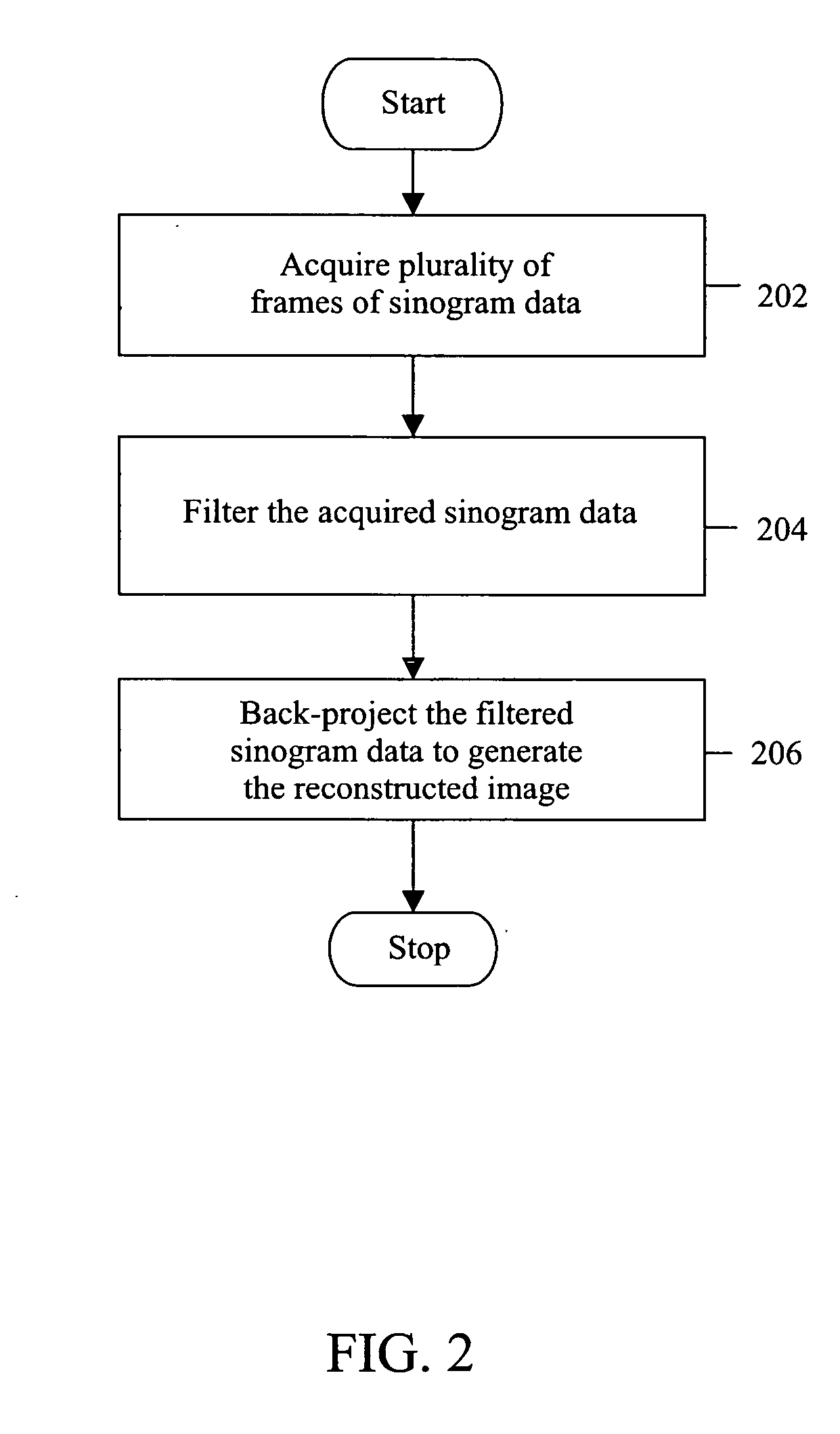
[0018] Various embodiments of the invention provide methods and systems to enable a Confidence-Weighted Back-Projection (CW BP) with filtering for Time-Of-Flight Positron Emission Tomography (TOF PET). The embodiments utilize an analytical filter to improve the quality of image by preventing blurring and distortion of the final output images.

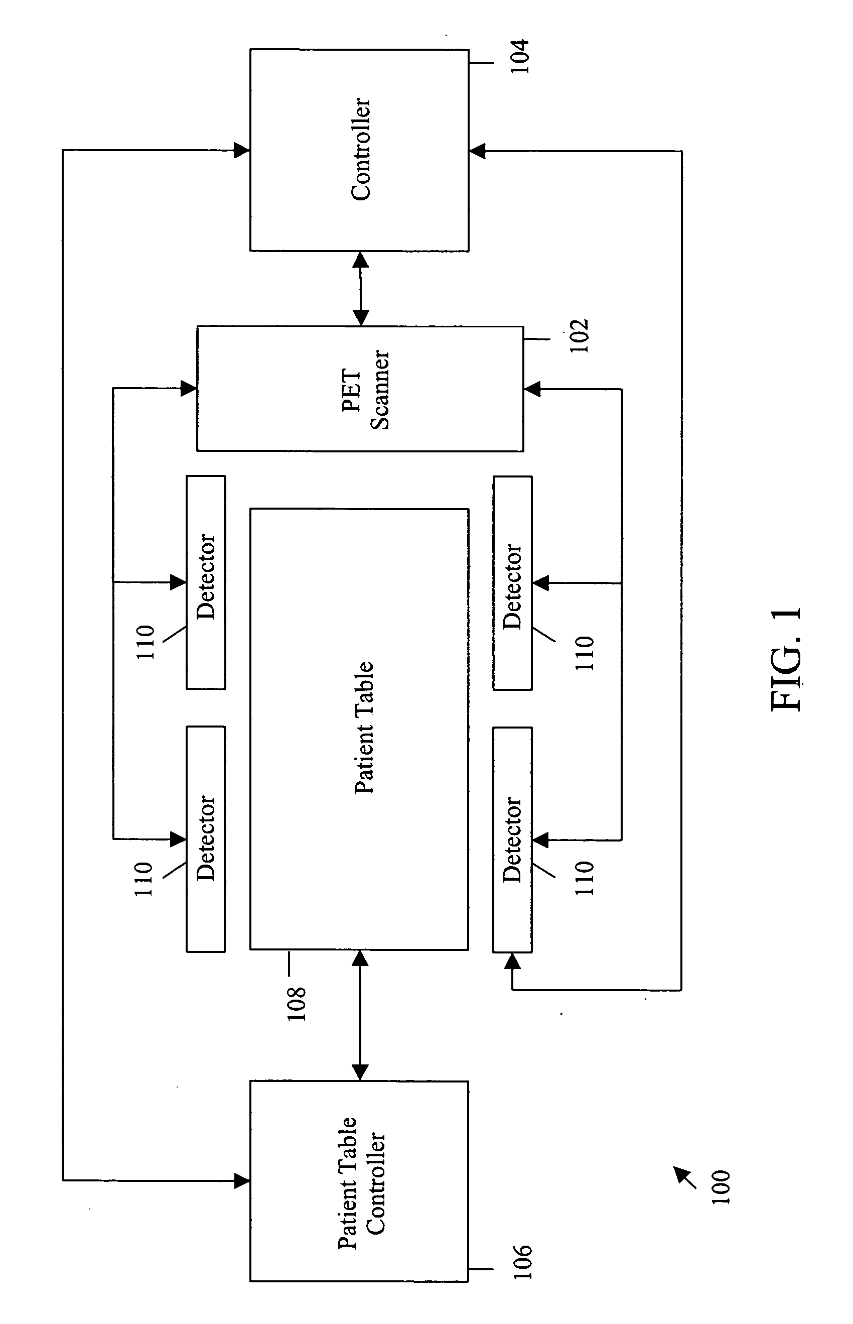
[0019]FIG. 1 is a block diagram of a PET system, in accordance with an exemplary embodiment of the invention. PET system 100 includes a PET scanner 102 and a controller 104. In accordance to various embodiments of the invention, PET system 100 further includes a patient table controller 106, a patient table 108 and PET detectors 110. Patient table 108 supports a patient, who is to be scanned, to acquire an image of the relevant portion of the body of the patient. Patient table 108 holds the patient within a viewable area of a plurality of detectors 110. Patient table 108 can be moved along a viewable area axis that is defined by detectors 110. ...


PUM


Abstract

Methods and systems for imaging by using a filter for Time-Of-Flight Positron Emission Tomography (TOF PET) are described. The described methods of imaging a patient by using a positron emission tomography (PET) system includes acquiring a plurality of frames of sinogram data, filtering the acquired sinogram data and back-projecting the filtered sinogram data to form an output image of the patient. The acquired sinogram data defines a line of response (LOR) and a time-of-flight (TOF) measurement that localizes positron annihilation within the patient. The filtering of the acquired sinogram data is performed using the TOF measurement.

Description

BACKGROUND OF THE INVENTION [0001] This invention relates generally to positron emission tomography (PET) systems, and more particularly, to the reconstruction of images in a Time-of-Flight PET (TOF-PET) system using an analytical filter. [0002] Positrons are positively charged electrons that are emitted by radionuclide substances. These radionuclide substances, called “radiopharmaceuticals”, are employed as radioactive tracers and are injected in a patient to be scanned. The radionuclide substances decay and emit positrons. The positrons collide with electrons in the patient's body and are annihilated. The annihilation process produces two gamma rays. These gamma rays are referred to as photons. The emitted photons are directed in nearly opposite directions, each with energy of 511 KeV. A PET scanner generates an image by determining the number of such annihilations at each location within a field of view. [0003] A PET scanner typically includes a detector ring assembly. This detec...

Claims


Application Information

Patent Timeline
Patent Type & Authority Applications(United States)
IPC IPC(8): G01T1/164
CPCG06T11/005
Inventor MANJESHWAR, RAVINDRA MOHANSTEARNS, CHARLES WILLIAM
Owner GENERAL ELECTRIC CO
Why Eureka
Try Eureka