

Partial-ring pet device and pet device
a technology of partial rings and pet devices, which is applied in the field of partial rings of pet devices and pet devices, can solve the problems of unsuitable mri imaging configuration and no space for radiation detectors under the measurement target, so as to reduce the missing of projection angles, reduce the artifacts of pet images, and improve the effect of image quality
- Summary
- Abstract
- Description
- Claims
- Application Information
AI Technical Summary
Benefits of technology
Problems solved by technology
Method used
Image

Examples
first embodiment
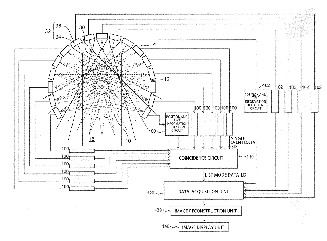
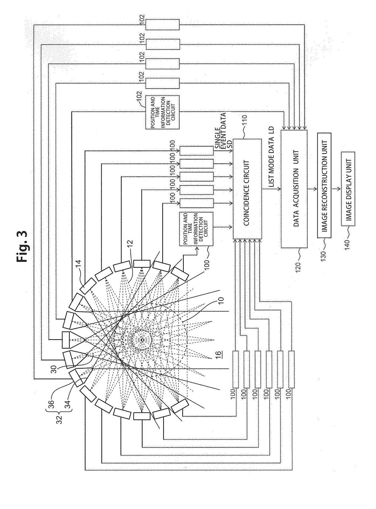
[0060]the present invention is a partial-ring PET device including coincidence detectors 14 for detecting lines of response 12 of annihilation radiations. As shown in FIG. 3, some (in FIG. 3, a lower part 16) of the coincidence detectors 14 to be arranged in a ring shape around a field of view 10 are missing. Collimator single gamma-ray radiation detectors (referred to as collimator detectors) 32 are arranged on an opposite side (upper side in the diagram) of the field of view 10 from the missing area 16 to compensate a drop in image quality due to the missing of the coincidence detectors 14. The collimator detectors 32 each include a pinhole collimator 34 for detecting either one of gamma-rays 30 of annihilation radiations occurring as a pair of gamma-rays as if the one is a single gamma-ray (referred to as “single gamma-ray detection”).
[0061]As shown in detail in FIG. 4, each collimator detector 32 includes a pinhole collimator 34 for letting only a single gamma-ray 30 of a predet...
second embodiment
[0077]Then, in the present invention, as shown in FIG. 10, Compton camera single gamma-ray radiation detectors (hereinafter, referred to as Compton cameras) 40 including scattering detectors 42 and absorption detectors 44 are used as single gamma-ray radiation detectors.
[0078]As shown in FIGS. 10 and 11, the Compton cameras 40 count events (referred to as Compton events) in which an incident single gamma-ray 30 causes Compton scattering in a scattering detector 42 and the resulting scattered radiation 43 is (photoelectrically) absorbed by an absorption detector 44. The Compton cameras 40 record the positions and energy of the interactions. If a single gamma-ray 30 causes Compton scattering in a scattering detector 42, the single gamma-ray 30 gives part of its total energy to the scattering detector 42, and changes its traveling direction at an angle (scattering angle) β corresponding to the given energy. If the traveling direction-changed gamma-ray (also referred to as scattered rad...
third embodiment
[0084]Unlike the collimator method, the Compton camera method is not intended to fully block the gamma-rays. Even if the scattering detectors 42 are placed in front of all the coincidence detectors 14, coincidence events can be obtained because of the presence of gamma-rays transmitted through the scattering detectors 42. As in a third embodiment shown in FIG. 13, the scattering detectors 42 therefore desirably cover a range as wide as possible unless a missing area is provided for the purpose of efficiently transmitting MRI signals or securing the patient's or subject's field of view.
[0085]The gamma-ray of a Compton event is an incident gamma-ray that causes Compton scattering and is counted by a scattering detector 42 and is (photoelectrically) absorbed and counted by an absorption detector 44. As shown in FIG. 13, the position of such a gamma-ray can be identified as being on a conical surface 46 the vertex angle of which is determined by the detected energy. Even if the scatteri...
PUM
 Abstract
Description
Claims
Application Information