Low risk deployment passenger airbag system

a passenger airbag and low-risk technology, applied in the direction of pedestrian/occupant safety arrangement, vehicle components, vehicular safety arrangments, etc., can solve the problems of high risk of injuries caused, occupants who are very close to the airbag, etc., to reduce the risk of neck injuries and reduce the risk of injuries

Inactive Publication Date: 2006-05-18
CIS TECH LLC
View PDF86 Cites 11 Cited by
  • Summary
  • Abstract
  • Description
  • Claims
  • Application Information

AI Technical Summary

Benefits of technology

[0004] Preferred embodiments of an airbag module of the present invention have a long curved housing that extends from the top portion to the mid (front) portion of the instrument panel. The length of the housing measured in the vehicle's longitudinal direction is extended long enough to provide substantially distributed airbag inflation force into the occupant and thus significantly reduce the risk of injuries caused by the airbag inflation as a result. The airbag system of the present invention can also provide a much safer mode of radial airbag deployment approximately following the instrument panel surface compared to the conventional airbag system. This safer mode of radial deployment can significantly reduce the risk of neck injuries that are commonly seen from the out-of-position testing using the conventional airbags.

Problems solved by technology

When the airbag cushion deploys, an out-of-position occupant who is very close to the airbag module at the time of the inflation can have a high risk of injuries caused by the concentrated force generated by the cushion deployment from the single location.

Method used


Image

  • Low risk deployment passenger airbag system
  • Low risk deployment passenger airbag system
  • Low risk deployment passenger airbag system

Examples


Embodiment Construction

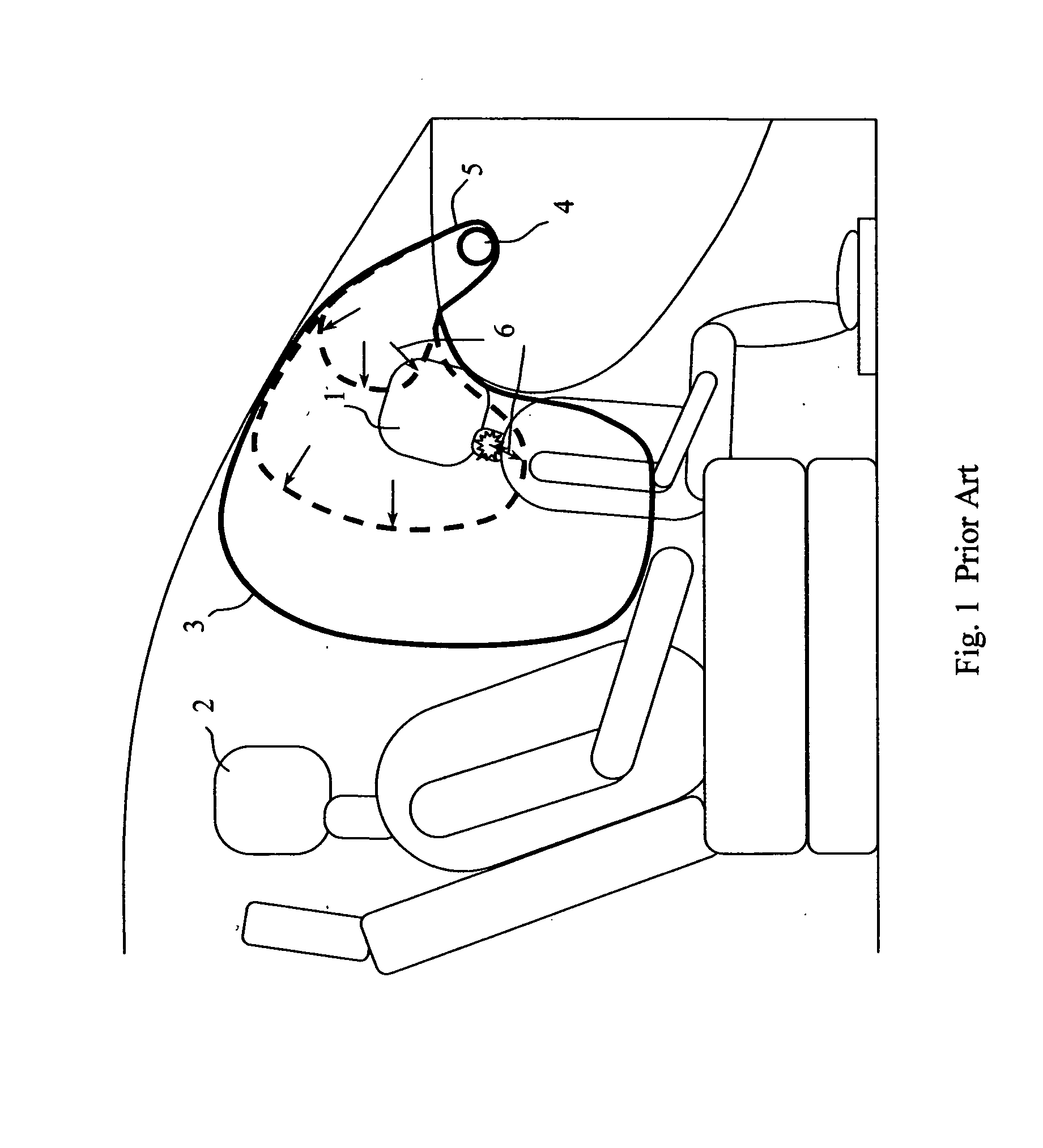
[0024]FIG. 1 shows a conventional passenger airbag module that is top-mounted in the instrument panel. The airbag cushion 3 deploys toward the head and torso areas of an adult occupant 2. During the airbag deployment, shown as dotted lines, the airbag can generate a substantially large component of downward deployment, as indicated by the arrows at 6. The component of downward deployment 6 can push the head of the out-of-position child 1 down and potentially cause a serious injury to the neck. The airbag module has a gas generating inflator 4, and a housing 5 that holds the inflator 4 and the airbag cushion 3.

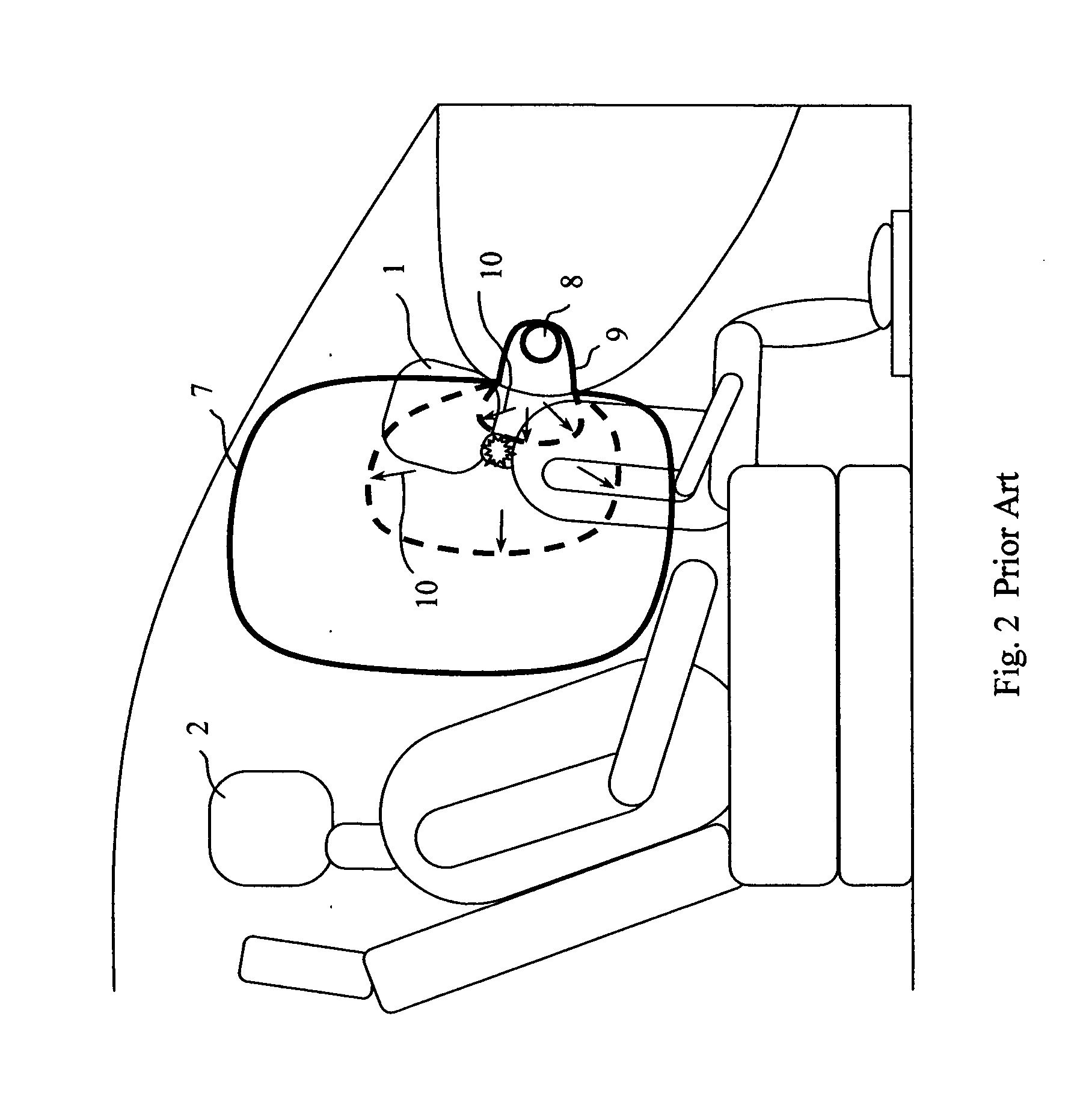
[0025]FIG. 2 shows another conventional passenger airbag module that is mid-mounted in the instrument panel. The airbag module includes an airbag cushion 7, which deploys toward the head and torso areas of an adult occupant 2. During the airbag deployment, shown as dotted lines, the airbag 7 can generate a substantially large component of upward deployment, as indicated by the...


PUM


Abstract

A passenger airbag system is designed for an automotive vehicle with a passenger compartment, a windshield and an instrument panel disposed between the passenger compartment and the windshield. The instrument panel has a top portion with a surface which is more horizontal than vertical and generally directed toward the windshield and a mid-portion with a surface that is more vertical than horizontal and generally directed toward an occupant of the passenger compartment. The system includes a single airbag housing that is disposed in the instrument panel and extends from the top portion to the mid-portion. The airbag cushion is deployable from the housing through the instrument panel along a predetermined path for direct contact with an occupant seated in the passenger compartment. The predetermined path is generally radial with respect to the surface of the instrument panel.

Description

REFERENCE TO RELATED APPLICATION [0001] This patent application claims benefit from U.S. Provisional Patent Application Ser. No. 60 / 628,434, filed Nov. 15, 2004, the entire content of which is incorporated herein by reference.FIELD OF THE INVENTION [0002] This invention relates to a passenger airbag system for use with a motor vehicle. More specifically, an airbag housing extends from a top portion of the instrument panel to a mid portion of the instrument panel as a single unit in such a way as to minimize the risk of injuries caused by airbag inflation to out-of-position occupants while maintaining as effective of protection for in-position occupants during serious crashes as a conventional airbag. BACKGROUND OF THE INVENTION [0003] The conventional passenger airbag modules are mounted at a single location on the instrument panel, i.e. top portion, mid (front) portion, or somewhere in between. When the airbag cushion deploys, an out-of-position occupant who is very close to the ai...

Claims


Application Information

Patent Timeline
Patent Type & Authority Applications(United States)
IPC IPC(8): B60R21/205
CPCB60R21/206B60R21/2165B60R21/261B60R2021/161
Inventor SONG, SEUNG-JAEJANG, MIYOUNGNAM, JONG SEOP
Owner CIS TECH LLC
Why Eureka
Try Eureka