Method and apparatus for controlling power drawn from an energy converter

a technology of energy converters and power supplies, applied in the field of energy conversion, can solve the problems of inefficient operation, waste of power, and inability to meet the requirements of dc load supply, and achieve the effect of reducing the number of power supply failures

Active Publication Date: 2006-05-18
SCHNEIDER ELECTRIC SOLAR INVERTERS USA
View PDF9 Cites 155 Cited by
  • Summary
  • Abstract
  • Description
  • Claims
  • Application Information

AI Technical Summary

Benefits of technology

[0014] The method may further involve performing the method periodically, and defining a period for performing the method periodically. Defining the period may include defining the period as a function of the power supplied to the load. The method may involve increasing the period when the power supplied to the load is relatively low and decreasing the period when the power supplied to the load is relatively high.

Problems solved by technology

Consequently, the 100 kHz perturb and observe frequency of most switching mode power supplies used to supply DC loads is too fast for applications where the load is an AC power grid.
However, decreasing the perturb and observe frequency can waste power, especially when changes in insolation occur.
During this period the full available power is not being drawn from the array resulting in inefficient operation.

Method used


Image

  • Method and apparatus for controlling power drawn from an energy converter
  • Method and apparatus for controlling power drawn from an energy converter
  • Method and apparatus for controlling power drawn from an energy converter

Examples


Embodiment Construction

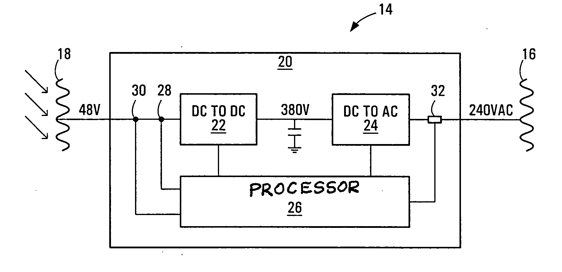
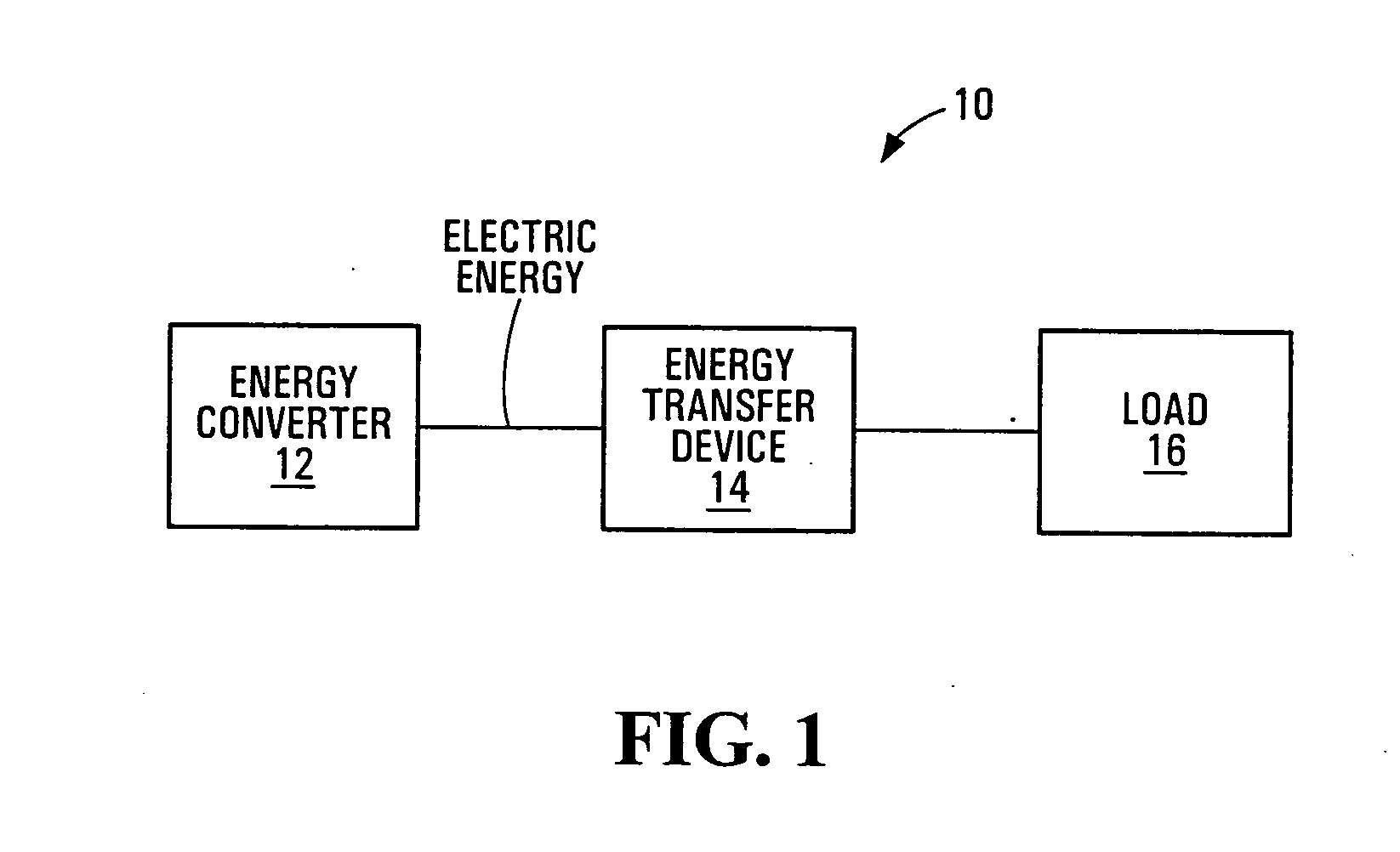
[0042] Referring to FIG. 1 an energy supply system according to a first embodiment of the invention is shown generally at 10. The system includes an energy converter 12 and an energy transfer device 14 which together cooperate to supply energy to a load 16.

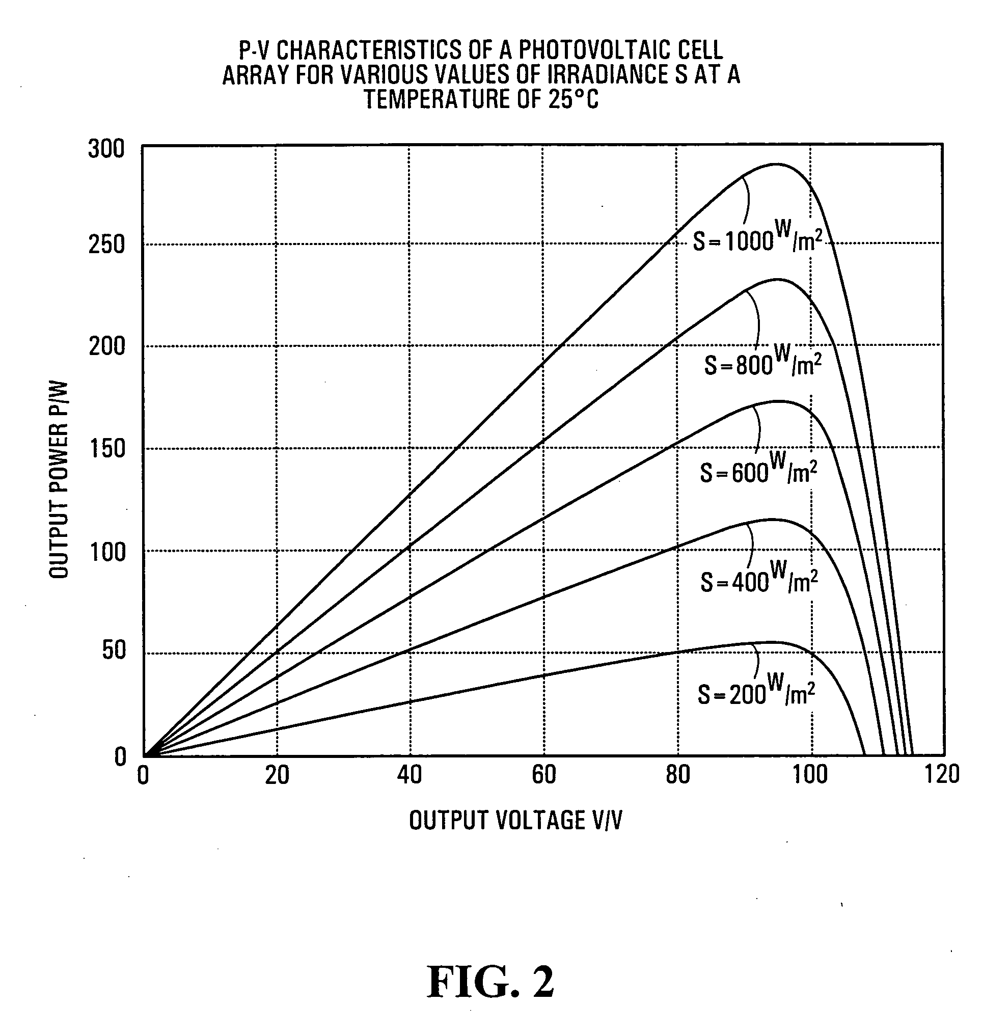
[0043] The energy converter 12 is of a general class of energy conversion devices that are able to supply electrical power in response to a supply of physical energy. Such devices are able to be operated under conditions where the supply voltage and supply current produced by the device are optimized such that for a given physical power input a maximum electrical power, i.e. a maximum working power is produced. The supply current and supply voltage conditions under which maximum working power can be extracted from the energy conversion device change depending upon the physical power available and operating conditions of the device.

[0044] For example, the energy converter 12 may include a photovoltaic array and the energy transfe...


PUM


Abstract

Methods, apparatus, media and signals for controlling power drawn from an energy converter to supply a load, where the energy converter is operable to convert energy from a physical source into electrical energy. Power drawn from the energy converter is changed when a supply voltage of the energy converter meets a criterion. The criterion and the change in the amount of power drawn from the energy converter are dependent upon a present amount of power supplied to the load. The methods, apparatus, media and signals described herein may provide improvements to DC to AC maximum power point tracking in an energy conversion system such as a photovoltaic power generation system.

Description

BACKGROUND OF THE INVENTION [0001] 1. Field of Invention [0002] This invention relates to energy conversion and more particularly to methods and apparatus for controlling power drawn from an energy converter operable to convert energy from a physical source into electrical energy. [0003] 2. Description of Related Art [0004] Energy conversion devices such as photovoltaic arrays are commonly used to provide power to electrical loads. Often these loads are direct current (DC) loads such as batteries, for example. Recently, efficiencies in power conversion devices are giving rise to solar power systems that supply power to an alternating current (AC) load such as an AC power grid such as may be operated by a public utility company. Such power systems may employ a photovoltaic array and an interface for converting power in a form received from the photovoltaic array into a form operable to be received by the AC power grid. Such an interface may involve a DC to AC inverter. [0005] Interfa...

Claims


Application Information

Patent Timeline
Patent Type & Authority Applications(United States)
IPC IPC(8): G05F1/10H02J3/38
CPCY02E10/563H02J3/385H02J3/383Y02E10/58H02J2300/26H02J2300/24H02J3/381Y02E10/56
Inventor CUTLER, HENRY H.
Owner SCHNEIDER ELECTRIC SOLAR INVERTERS USA
Why Eureka
Try Eureka