Systems and methods for wirelessly determining vehicle identification, registration, compliance status and location

a technology of vehicle identification and wireless determination, applied in the field of system and method for wireless determination of vehicle identification, registration, compliance status and location, can solve the problems of limited text data retrieval options of radar units, unable to print out text data, and unable to obtain speed information from radar devices onsite and on demand, so as to facilitate the coordination of tags

Inactive Publication Date: 2006-05-18
ORTIZ & LOPEZ PLLC
View PDF8 Cites 30 Cited by
  • Summary
  • Abstract
  • Description
  • Claims
  • Application Information

AI Technical Summary

Benefits of technology

[0015] In accordance with a feature of the present invention, a CPU can assists with Tag coordination. Modern motor vehicles include a CPU (computer board and circuitry) within the engine block. An RF tag can also be integrated with the engine CPU or can coordinate with the engine computer. Use of several tags, including the VIN plate and engine tags can ensure that a motor vehicle's identity is preserved. Thieves will not likely be able to disable vehicle identify capabilities where several, hard to reach, tags are used. All tags can be operable as the Responder.

Problems solved by technology

For many years governmental agencies and law enforcement could only obtain from officers in the field with hand held or dash mounted radar systems the speed of a nearby vehicle.
The Radar units were limited with minimal data retrieval options and could not print out text data.
Currently, law enforcement agencies purchase standard speed radar units that only provide users the ability to know the speed of the vehicle that the radar device was pointed at.
Agencies have not yet been able to print out speed information from the radar device onsite and on demand.
The level of thefts of vehicles globally is an economic problem that is costing citizens and insurance companies billions of dollars each year.
Finally, many city and state governments are currently strapped with financial burdens.

Method used


Image

  • Systems and methods for wirelessly determining vehicle identification, registration, compliance status and location
  • Systems and methods for wirelessly determining vehicle identification, registration, compliance status and location
  • Systems and methods for wirelessly determining vehicle identification, registration, compliance status and location

Examples


Embodiment Construction

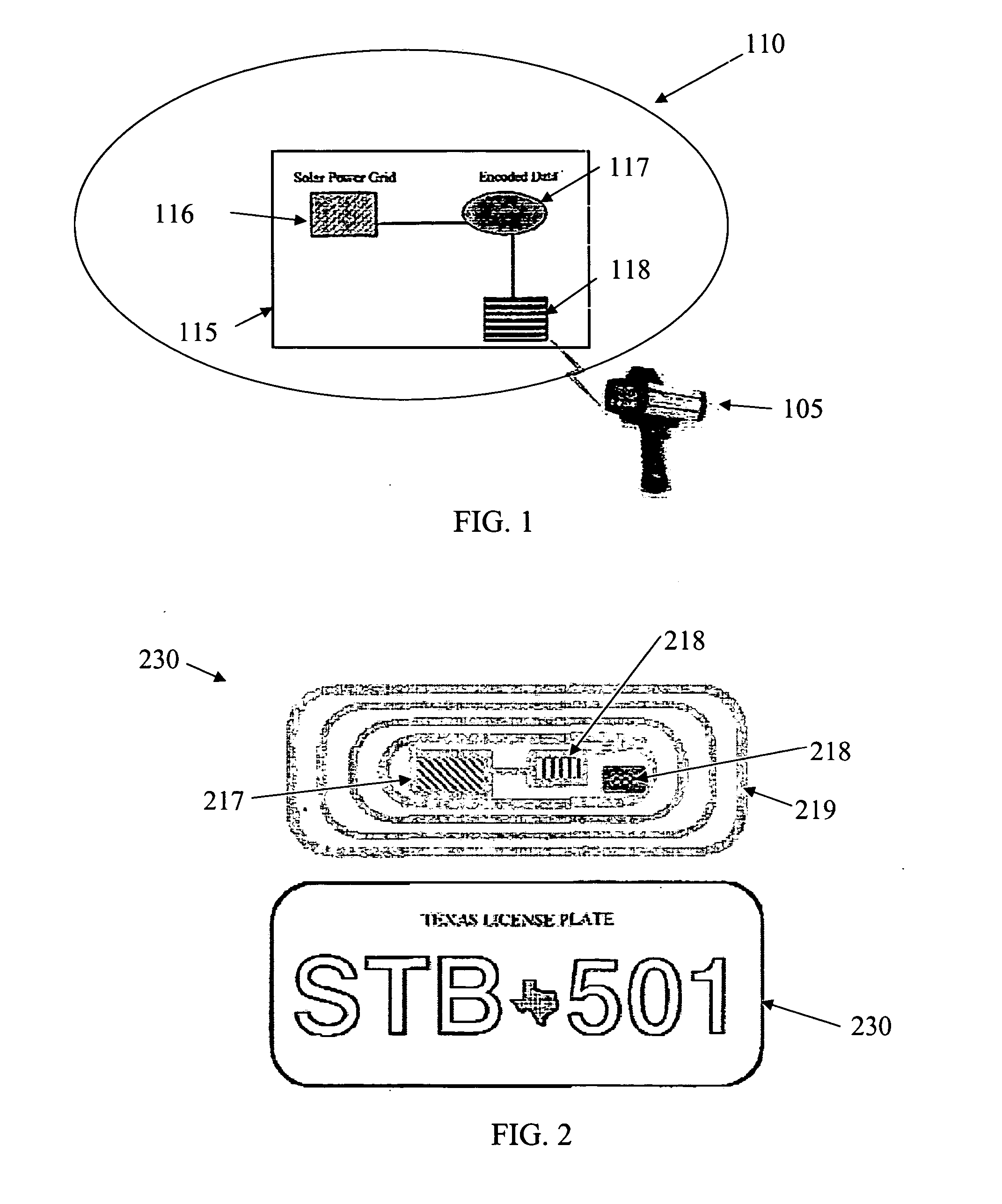
[0025] Referring to FIG. 1, illustrates the system architecture for supporting a radar initiated vehicle mounted rf tag challenger, which can be referred to as a “challenging system”. As shown in the FIG. 1, a radar source 105 (which can be referred to as the “challenger”) transmits a signal towards a vehicle 110, which contains an rf tag 115 mounted therein. The rf tag 115 includes a power source 116, a memory 117 with encoded data and a transceiver 118 for receiving the radar challenge from the radar source 101 and transmitting data from the memory with encode data 117 back to the radar source 101. The power source 116 can include a battery, solar powered cell, vehicle power connection, or any combination thereof. The radar tag electronic can includes components and circuitry known in the art, but must have a memory carrying relevant data, transceiver for receiving a challenge and transmitting data and power source.

[0026] It should be appreciated that the rf tag 115 can be mounte...


PUM


Abstract

A radar unit as a Challenger communicates with ref tag-enabled media (e.g., registration stickers, licensed plates, physical VIN tags) associated with motor vehicles to obtain vehicle-related data, e.g., vehicle identification numbers, states registration status, vehicle inspection status, insurance expiration, amber alert status, license tag / plate information and additional features are a particularly unique features of interested to government and private entities. The radar challenger can be integrated with a radar unit used by law enforcement to obtain vehicle speed in addition to vehicle-related data. Data can be transmitted over network to agencies and private entities.

Description

INVENTION PRIORITY [0001] The present invention claims the benefit of U.S. Provisional Patent Application No. 60 / 520,869 entitled “systems and methods for wirelessly determining vehicle identification, registration, compliance status and location,” which was filed on Nov. 17, 2003.FIELD OF THE INVENTION [0002] The present invention is related to: managing vehicle identification numbers (VIN), motor vehicle registrations, emission compliance, speed monitoring, radar, Rf Tag (tagging), Global positioning system (GPS) integration, location determination, motor vehicle security / retrieval, and radar initiated challenge / response of rf tags. BACKGROUND [0003] For many years governmental agencies and law enforcement could only obtain from officers in the field with hand held or dash mounted radar systems the speed of a nearby vehicle. The Radar units were limited with minimal data retrieval options and could not print out text data. Currently, law enforcement agencies purchase standard spee...

Claims


Application Information

Patent Timeline
Patent Type & Authority Applications(United States)
IPC IPC(8): G01S13/74
CPCG01S13/74G01S13/92G08G1/017
Inventor POWELL, STEVEN W.ORTIZ, LUIS M.
Owner ORTIZ & LOPEZ PLLC
Why Eureka
Try Eureka