Scanning device

a scanning device and scanning technology, applied in the field of scanning devices, can solve the problems of reducing the acceptance level and affecting the scanning quality, and achieve the effect of improving the scanning quality

Inactive Publication Date: 2006-05-18
BENQ CORP
View PDF7 Cites 4 Cited by
  • Summary
  • Abstract
  • Description
  • Claims
  • Application Information

AI Technical Summary

Benefits of technology

[0008] It is therefore the object of the invention to provide a scanning device capable of keeping a constant distance between image sensor and the glass on the scanning platform to improve image scanning quality.

Problems solved by technology

A commonly encounter problem for scanner using contact image sensor is that the contact image sensor is unable to keep a constant distance with the scanner and maintain the scanning depth stable, greatly affecting the scanning quality and reducing the acceptance level.

Method used


Image

  • Scanning device
  • Scanning device
  • Scanning device

Examples


first embodiment

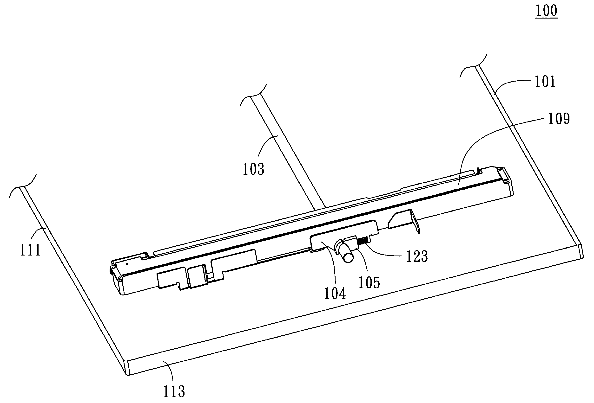
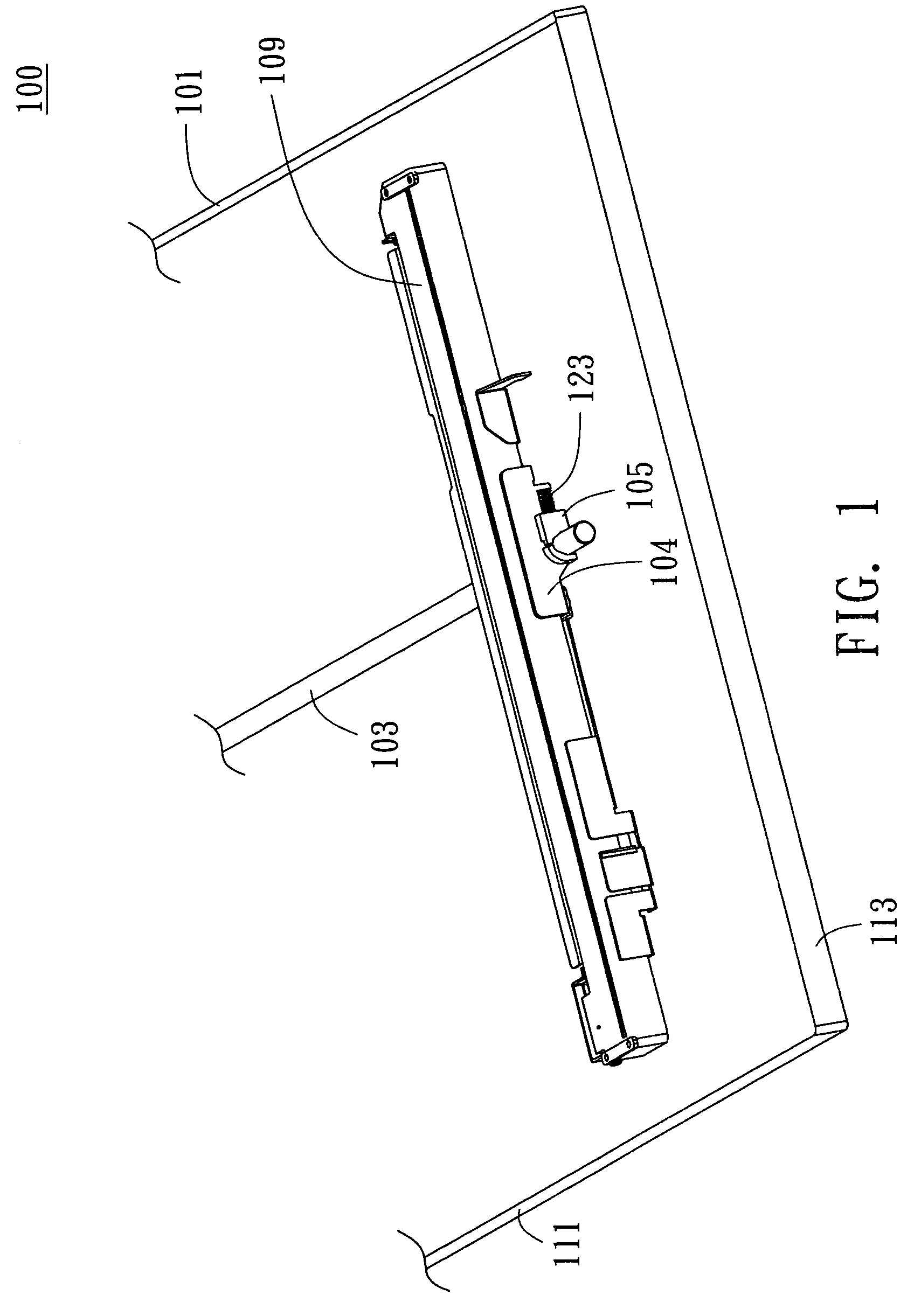
[0020] Referring to FIG. 1, a three-dimensional diagram of a scanning device is shown. The scanning device 100 includes a scanning platform 101, a bar 103, a carriage 104, a contact image sensor 109, a positioning member 105 and an elastic member 123. The scanning platform 10 is for placing a document and has a first edge 111 and a second edge 113. The first edge 111 and the second edge 113 define a plane normal direction 115. The bar 103 is parallel to the first edge 111 and is disposed below the scanning platform 101. The contact image sensor 109 can be a contact image sensor for instance in present embodiment. The elastic member 123 can be a spring or an elastic piece for instance in present embodiment.

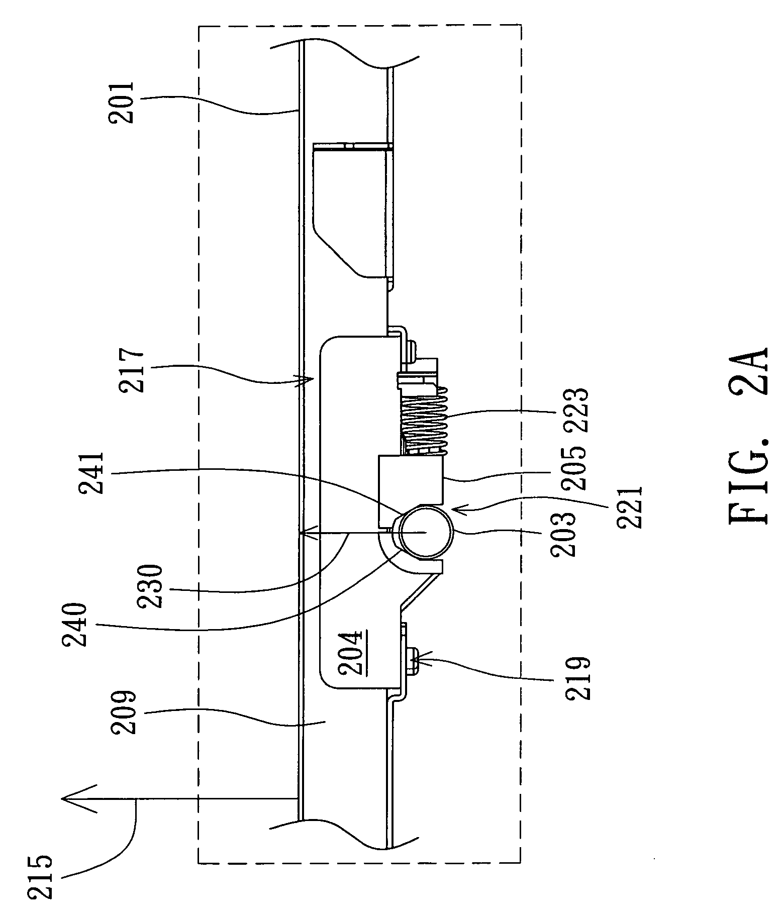
[0021] Referring to FIG. 2A, a front view showing the bar and the scanning platform keep a standard distance is shown. The carriage 204 has a bottom surface 219 and a top surface 217. The top surface 217 faces a scanning platform 201. The bottom surface 219 has a receiving part 22...

second embodiment

[0025] Referring to FIG. 3, a three-dimensional diagram showing the second embodiment has two pivotal parts is shown. The present embodiment differs with the first embodiment in that the positioning member rotates to press against the bar. As shown in FIG. 3, scanning device in present embodiment includes a bar 303, a carriage 304, an elastic member 323a, and two positioning members 305a and 305b. In the present embodiment, the positioning members 305a and 305b are rotatably mounted on the spindle 370. With the spindle 370 being received in axial holes 324 of the positioning member 305a and 305b, the positioning members 305a and 305b are able to rotate around the spindle 370. Like the first embodiment, when the distance between the bar 303 and the scanning platform 301 is smaller than or larger than the standard distance, the elastic member 323a provides an elastic force to the positioning members 305a and 305b, enabling the positioning member 305a and 305b to rotate to press or loo...

third embodiment

[0026] Referring to FIG. 4A, FIG. 4B and FIG. 4C together. FIG. 4A is a three-dimensional assembly diagram of the third embodiment, FIG. 4B is an exploded diagram of the third embodiment, and FIG. 4C is a cross-sectional diagram along the cross-sectional line 4C-4C′ of FIG. 4B. The present embodiment differs with the first embodiment and the second embodiment in that a receiving slot 456. The receiving slot 456 is disposed on the top surface 417 of the contact image sensor 409. The receiving slot 456 has a hole 473, enabling the positioning member 405 to be immediately adjacent to the contact image sensor 409. Like the first and the second embodiments, when the distance between the bar 403 and the scanning platform is smaller than the standard distance during scanning, implying that the compression between the carriage 404 and the scanning platform is too heavy. Meanwhile, the carriage 404 would be pushed downwards by the scanning platform. When the positioning member 405 presses ag...


PUM


Abstract

A scanning device including a scanning platform, a bar, a carriage, a contact image sensor, a positioning member and an elastic member is provided. The bar disposed below the scanning platform is parallel to the first edge. The carriage has a bottom surface and a top surface. The bottom surface has a receiving part for receiving the bar. The top surface faces the scanning platform. The carriage is slideably moved below the scanning platform along the bar. The contact image sensor disposed on the top surface is for scanning a document. The positioning member which is slideably or rotatably disposed on the bottom surface is for pressing against the bar. The elastic member is connected to the carriage and the positioning member and provides an elastic force to the positioning member. The elastic force transmitted to the bar enables the contact image sensor to press the scanning platform tightly.

Description

[0001] This application claims the benefit of Taiwan application Serial No. 93135502, filed Nov. 18, 2004, the subject matter of which is incorporated herein by reference. BACKGROUND OF THE INVENTION [0002] 1. Field of the Invention [0003] The invention relates in general to a scanning device, and more particularly to a scanning device capable of maintaining a constant distance between a contact image sensor and a scanning platform. [0004] 2. Description of the Related Art [0005] Scanning quality is crucial to the competitiveness of scanner. Scanners are divided into two types according whether a charged coupled device or a contact image sensor is used. [0006] The advantage of the scanner using contact image sensor is that the contact image sensor can be modularized. For example, the light source, the sensor and the amplifier can be integrated. The structure and theory of the scanner using contact image sensor are very simple, the manufacturing cost can be largely reduced. Furthermo...

Claims


Application Information

Patent Timeline
Patent Type & Authority Applications(United States)
IPC IPC(8): H04N1/04
CPCH04N1/1013H04N1/103H04N2201/0442H04N2201/0456
Inventor QIAN, MING-KUAN
Owner BENQ CORP
Why Eureka
Try Eureka