[0019] It is an object of the invention to provide an improved connector which overcomes all the disadvantages of the prior art and which ensures a stable holding force for a flexible printed circuit board even with less contacts without causing defective or failed connection and achieves further reduced overall height of the connector.
[0027] As can be seen from the above description, the connector 10 according to the invention brings about the following significant effects.
[0029] Therefore, a simple construction of the locking members 18 ensures sufficient displacements of the engaging portions 24 of the locking members 18 and can reduce the overall height by about 0.13 to 0.17 mm.
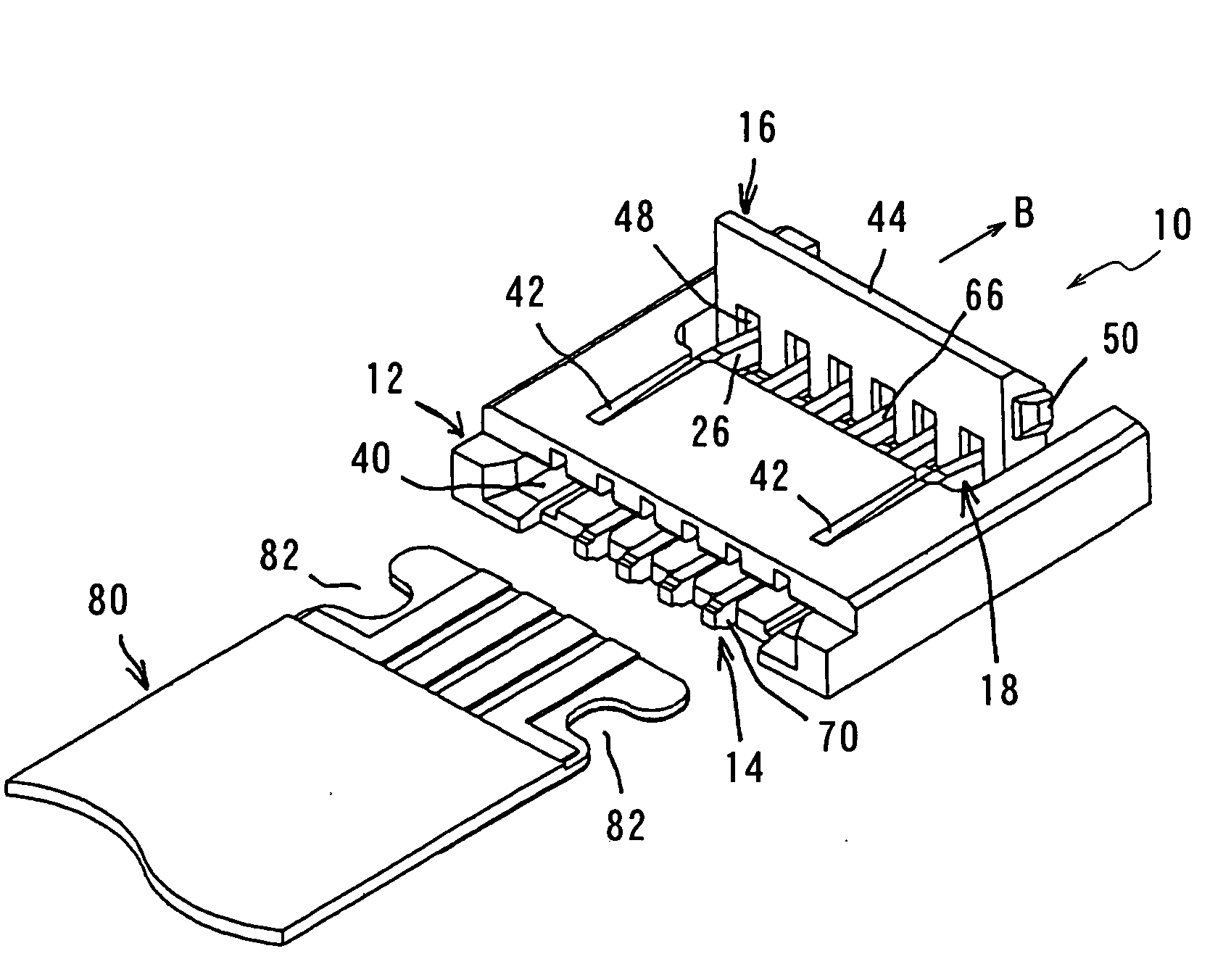
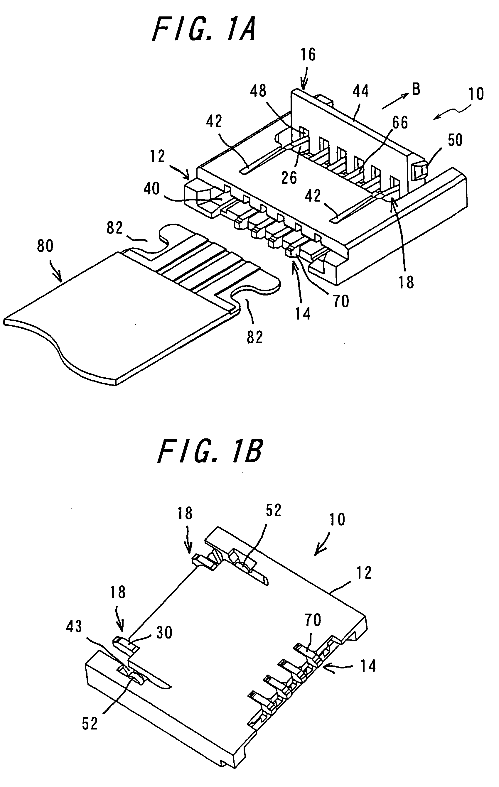
[0030] (2) In a connector 10 detachably fitted with a flexible printed circuit board 80, including a plurality of contacts 14 each having a contact portion 64 to contact the flexible printed circuit board 80, a housing 12 holding and fixing the contacts 14 and having a fitting opening 40 into which the flexible printed circuit board 80 is inserted, locking members 18 adapted to engage the flexible printed circuit board 80, and a pivoting member 16 causing the contacts 14 and the locking members 18 to be elastically deformed, according to the invention the flexible printed circuit board 80 is provided with anchoring portions 82, and the locking members 18 each comprise a first piece 20 having an engaging portion 24 at one end adapted to engage the anchoring portion 82 of the flexible printed circuit board, a pressure receiving portion 26 at the other end adapted to be urged by the pivoting member 16, and a projection 34 inwardly extending from the tip of the pressure receiving portion 26; a second piece 22 having a connection portion 30 at one end to be connected to a substrate; and a jointing fulcrum portion 32 for connecting the first piece 20 and the other end of the second piece 22; the locking members 18 being installed on the housing 12, and further the second pieces are void of parts at positions facing to the engaging portions 24 of the first piece when the pivoting member 16 is pivotally moved to bring the engaging portions 24 of the locking members 18 into engagement with the anchoring portions 82 of the flexible printed circuit board 80. Accordingly, a simple construction of the locking members 18 ensures sufficient displacements of the engaging portions 24 of the locking members 18, and the connector 10 according to the invention can achieve a stable holding force fully complying with customer's requirements for a flexible printed circuit board and hence provide stable connection.
[0032] (4) According to the invention, the second pieces 22 each include an extension portion 28 extending from the jointing fulcrum portion 32 in such a direction that the extension portion faces to the engaging portion 24, and the length of the extension portion 28 is shorter than the distance from the jointing fulcrum portion to the engaging portion 24 so that the extension portions 28 stop short of the positions facing to the engaging portions 24 when the pivoting member 16 is pivotally moved to bring the engaging portions 24 of the locking members 18 into engagement with the anchoring portions 82 of the flexible printed circuit board 80. Therefore, as there are provided the notches 42 in the upper surface of the housing 12, a simple construction of the locking members 18 ensures sufficient displacements of the engaging portions 24 of the locking members 18, and the connector according to the invention can achieve a stable holding force fully complying with customer's requirements for a flexible printed circuit board and hence provide stable connection and further can reduce the overall height of the connector by approximately 0.2 mm.
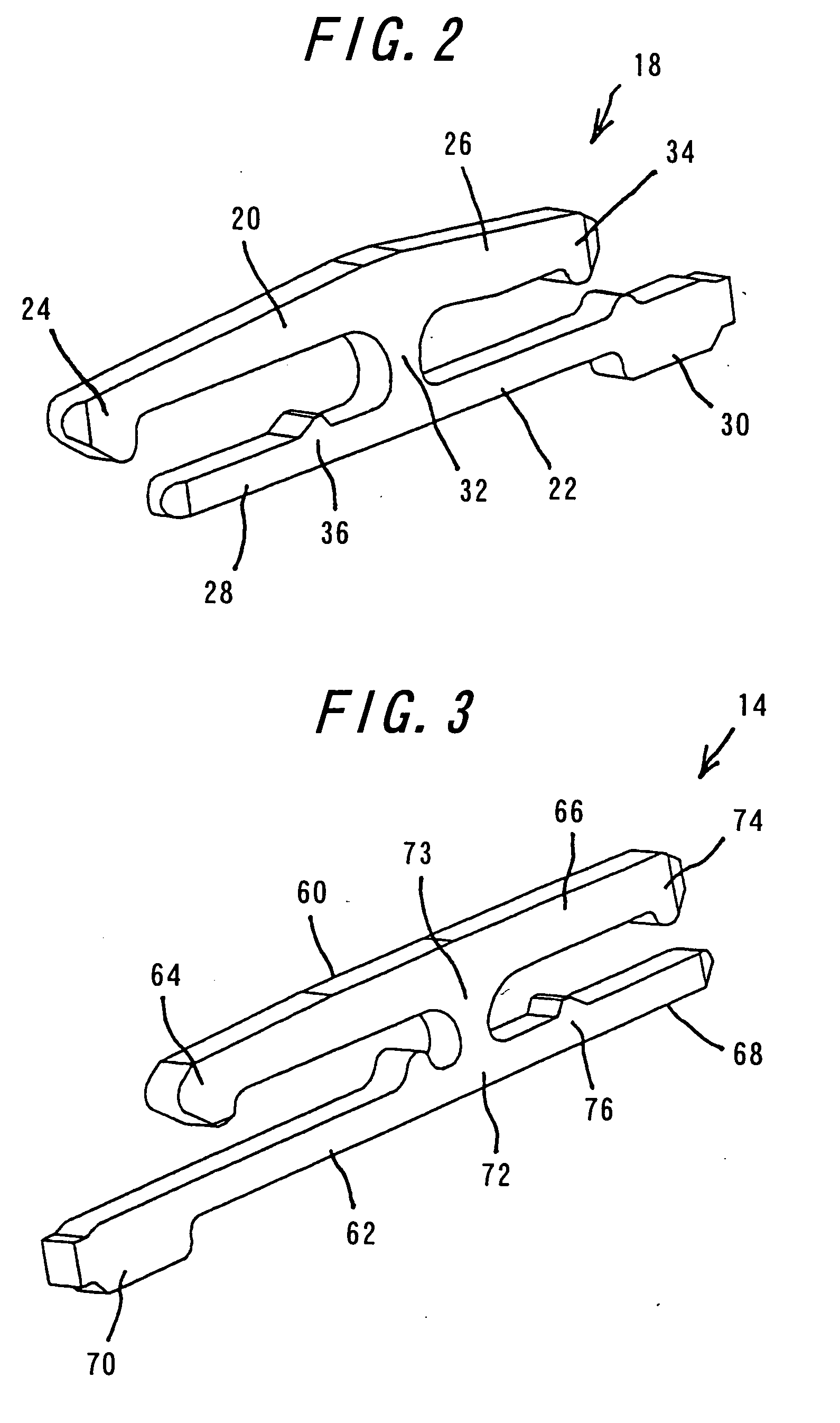
[0034] (6) According to the invention, the contacts 14 each comprise a first piece 60 having a contact portion 64 at one end adapted to contact the flexible printed circuit board 80, a pressure receiving portion 66 at the other end adapted to be urged by the pivoting member 16, and a projection 74 inwardly extending from the tip of the pressure receiving portion 66; a second piece 62 having a connection portion 70 at one end to be connected to a substrate and at the other end an extension portion 68 extending from a fulcrum portion 72; and a jointing portion 73 for connecting the first piece 60 and the fulcrum portion 72 of the second piece 62; the contact portion 64, the jointing portion 73, the fulcrum portion 72, and the connection portion 70 are arranged substantially in the form of a U-shape, and further the pivoting member 16 comprises an actuating portion 44 for pivotally moving the pivoting member, urging portions 46 arranged continuously in the longitudinal direction, and anchoring holes 48 into which the pressure receiving portions 66 and 26 of the contacts 14 and the locking members 18 can be inserted, and the pivoting member 16 is installed on the housing 12 so that the urging portions 46 are pivotally moved between the pressure receiving portions 66 and the extension portions 68 of the contacts 14 and between the pressure receiving portions 26 and the connection portions 30 of the locking members 18. Accordingly, it is possible to provide a connector 10 which requires no force for inserting a flexible printed circuit board 80 with the aid of the simple construction of the contacts 14 similar to the locking members 18.

