
Suture anchor

a suture anchor and anchor technology, applied in the field of surgical fixation devices, can solve the problems of surgeons being one of the more difficult steps

Active Publication Date: 2006-05-18
BANNERMAN BRETT
View PDF69 Cites 582 Cited by
  • Summary
  • Abstract
  • Description
  • Claims
  • Application Information

AI Technical Summary

Benefits of technology

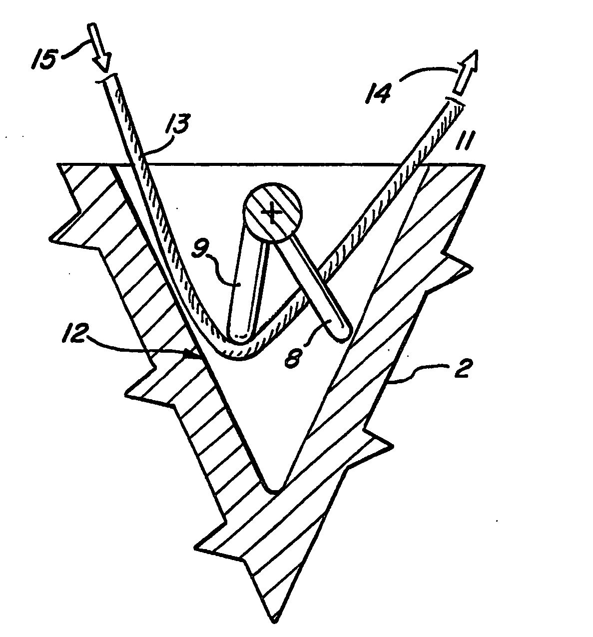
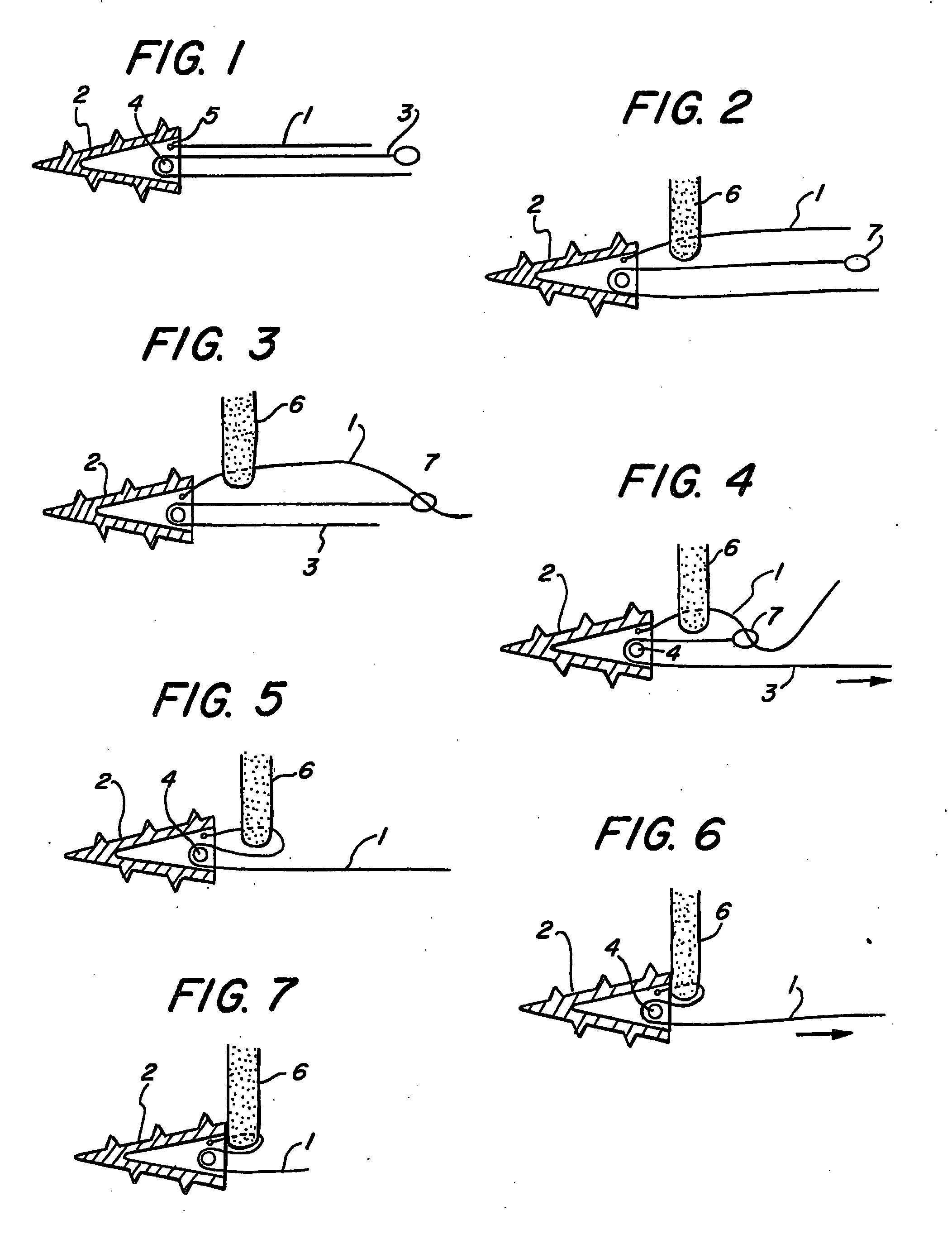
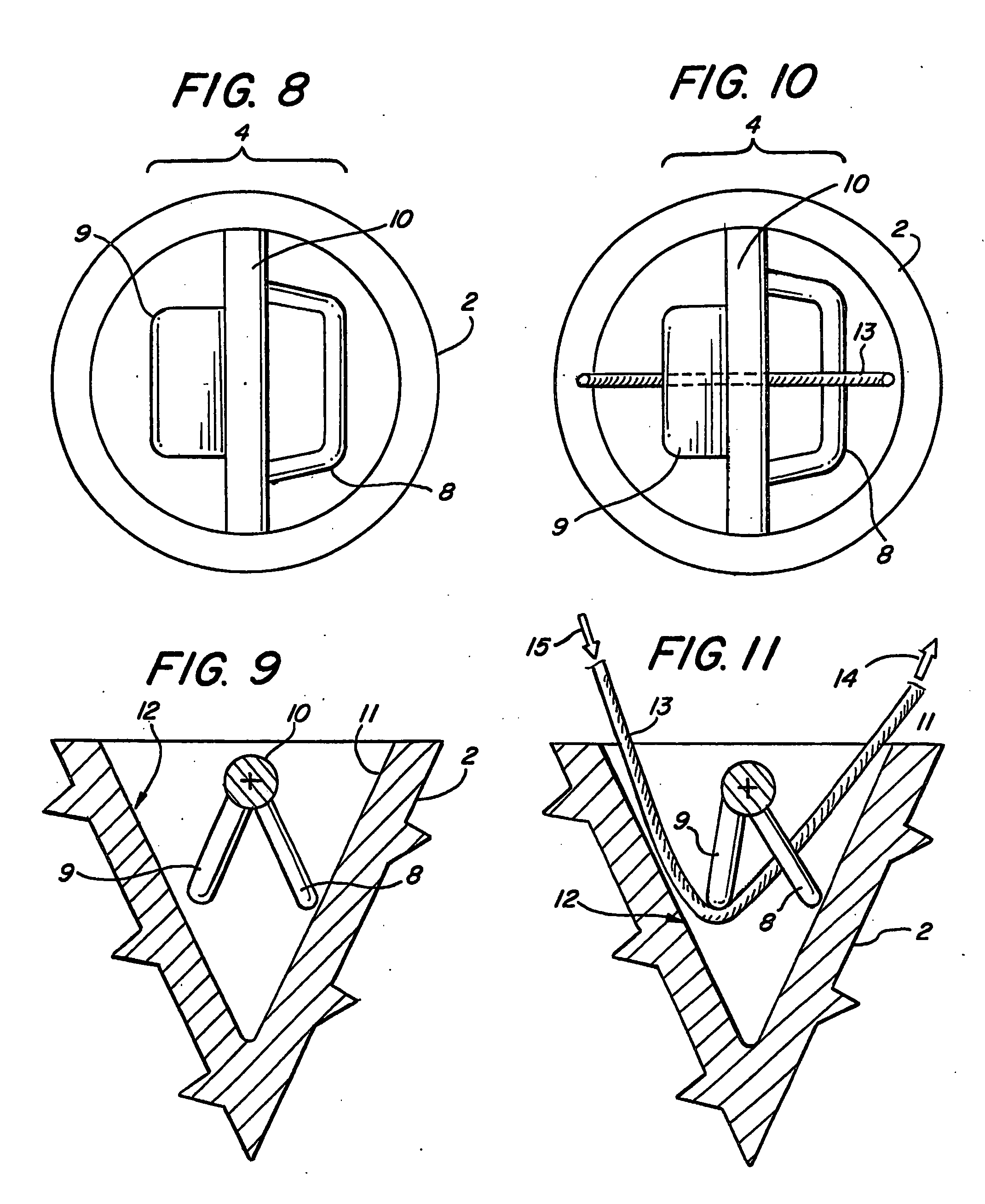
[0008] In one aspect, the invention is a suture anchor for securing nearby tissue to bone, the suture anchor comprising an anchor body having an axis and a proximal end that is substantially transverse to the axis; means for anchoring the anchor body to the bone of the patient; an elongated suture puller slidably located in the anchor body with first and second lengths extending therefrom, the second length including means for engaging suture; suture connected to the second length of the elongated suture puller via the means for engaging whereby the suture may be pulled into and through the anchor body behind the elongated suture puller when the elongated suture puller is pulled outward therefrom via the first length; and a suture locking mechanism that substantially prevents the suture from moving in at least a first direction after being pulled into and through the anchor body by the elongated suture puller.

Problems solved by technology

The last step, knot tying, is very critical and for many surgeons one of the more difficult steps.

Method used


Image

  • Suture anchor
  • Suture anchor
  • Suture anchor

Examples


Embodiment Construction

[0126] In accordance with at least one embodiment of the present invention, an anchor is presented with an elongated suture puller (aka a shuttle) to thread suture through the locking mechanism located in the anchor's center. The anchor in this embodiment as with all the presented designs can be embodied in an anchor having an anchor body with any suitable means for anchoring the anchor body to the bone of a patient. The anchoring means includes, for example, a push-in, screw-in, eared, or other styles of implant. FIG. 1 shows a screw-in style anchor as an example.

[0127] A strand of Suture 1 is affixed to the Anchor Body 2 at an Affixation Point 5. The Affixation Point 5 is shown as a method of how the suture can be attached to the anchor. A Locking Mechanism 4 is shown schematically in the Anchor Body 2 that has a bias to allow the Suture 1 or elongated suture puller 3 having first and second lengths extending from the anchor body to slide in one direction but not the other. For t...


PUM


Abstract

A suture anchor (e.g. 100) for knotlessly securing nearby tissue to bone is formed from an anchor body (e.g. 101 / 102) that includes a mechanism for being securely anchored to the bone, an elongated suture puller (e.g. 122) extending through the anchor body with a proximal end for being pulled in a proximal direction by a surgeon and a distal end (e.g. 125) with a suitable mechanism for engaging suture (e.g. 127), suture (e.g. 132) carried by the engaging mechanism (e.g. 127) at the distal end (e.g. 125) of the elongated suture puller (e.g. 122), and a suture locking mechanism (e.g. 110) that substantially prevents the suture (e.g. 122) from moving in at least a first direction after being pulled into and through the anchor body (e.g. 101 / 102) by the elongated suture puller (e.g. 122).

Description

CROSS REFERENCE TO RELATED APPLICATIONS [0001] This application claims the benefit of Provisional Application Ser. No. 60 / 613877 filed on Sep. 28, 2004, entitled “SUTURE ANCHOR,” which application is fully incorporated herein by reference.BACKGROUND OF THE INVENTION [0002] 1. Field of the Invention [0003] This invention relates generally to surgical fixation devices and, more specifically, to medical implants known as suture anchors that are used to attach soft tissue to hard tissue via a strand of suture in order to implement a repair. The following disclosure presents several suture anchor designs that will greatly simplify the attachment step of this repair by eliminating the need to create a knot. [0004] 1. Discussion of Related Art [0005] A common surgical procedure is to repair an injury by re-attaching soft tissue to bone. This surgical attachment is required to hold the soft and hard tissues together until the body's natural healing response permanently attaches the two toge...

Claims


Application Information

Patent Timeline
IPC IPC(8): A61B17/04
CPCA61B17/0401A61B17/0485A61B17/0487A61B17/0642A61B2017/044A61B2017/0448A61B2017/0451A61B2017/0456A61B2017/0458A61B2017/0496
Inventor WEISEL, THOMASPADGET, MARTINSKINLO, DAVIDBANNERMAN, BRETT
Owner BANNERMAN BRETT
Learn More