Fuel cut off valve

a fuel cut off valve and cutoff valve technology, applied in the field of fuel cut off valves, can solve the problems of reduced seal performance, poor reopening performance of the fuel cut off valve in the full fuel control valve, and large floats, and achieve excellent sealing properties

Inactive Publication Date: 2006-05-25
TOYODA GOSEI CO LTD
View PDF8 Cites 38 Cited by
  • Summary
  • Abstract
  • Description
  • Claims
  • Application Information

AI Technical Summary

Benefits of technology

[0009] An advantage of some aspects of the invention is to provide a fuel cut off valve that is able to pro

Problems solved by technology

Because of this, the positioning of the upper part main unit is not stable, leading to a problem with reduced seal performance due to the upper valve unit being off-center in the seal part of the connecting passage.
Additionally, there has been a problem in that the floats have tended to be large due to the need for increasing the upwards force of the float in order to close from a state wherein the upper valve unit is off-center.
Given this, as a structure for solving this problem, a fuel cut off valve has been disclosed wherein a float and a upper valve unit disposed at the upper part of the float are provided, where an recessed part of t

Method used


Image

  • Fuel cut off valve
  • Fuel cut off valve
  • Fuel cut off valve

Examples


first embodiment

A. First Embodiment

(1) Schematic Structure of the Fuel Cut off Valve 10

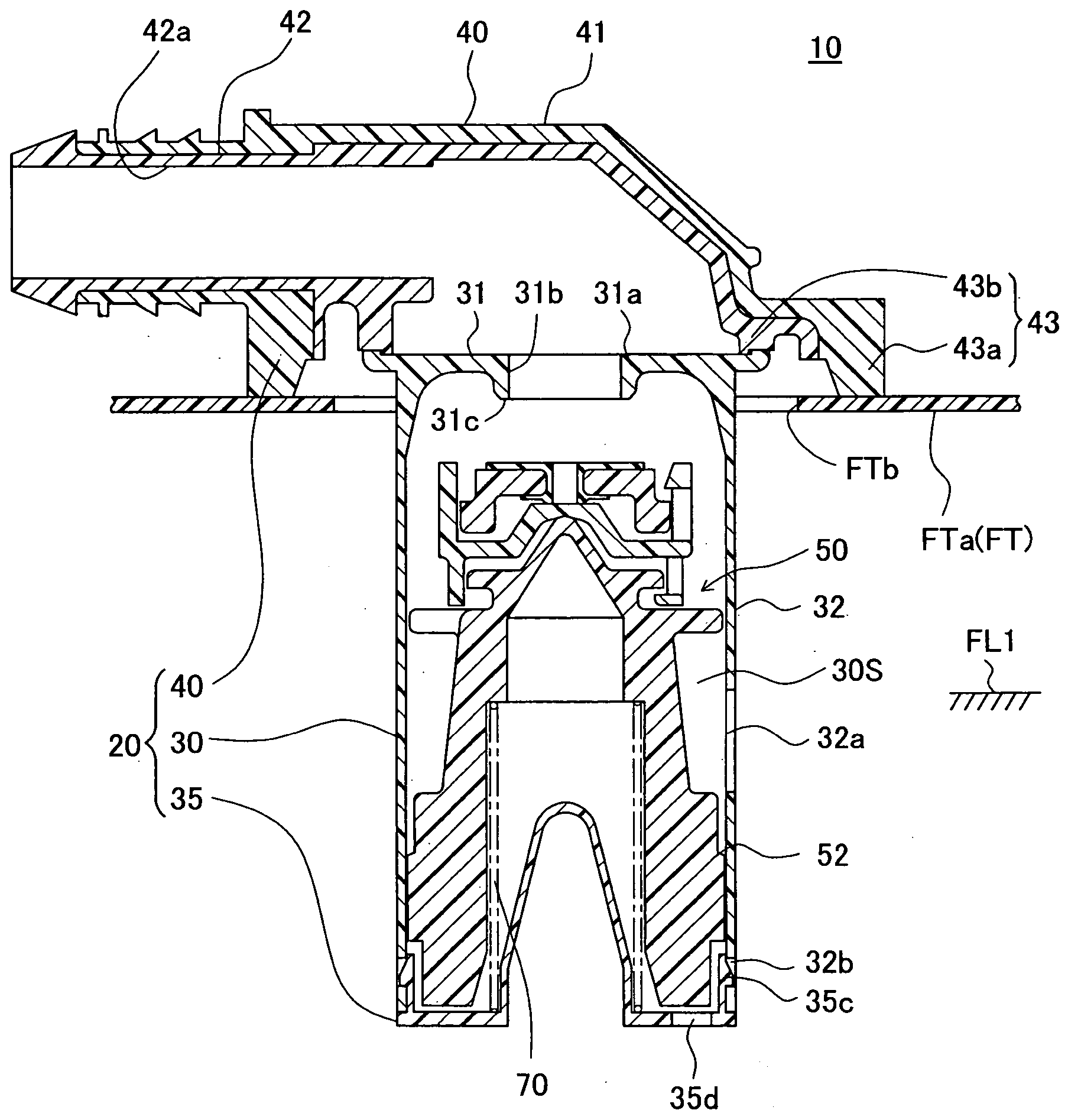
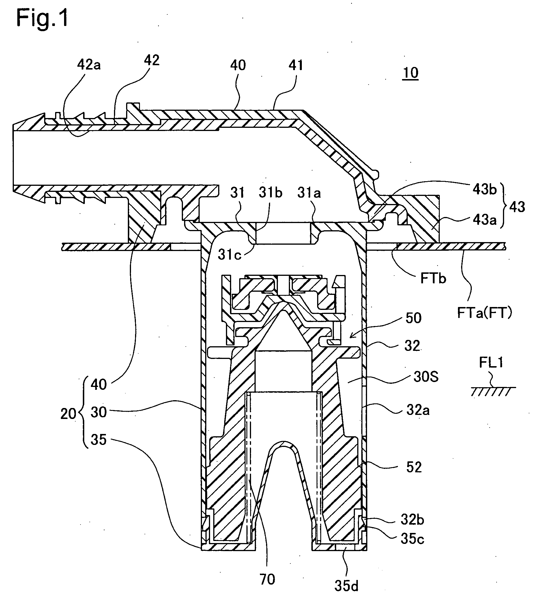
[0048]FIG. 1 is a cross-sectional view illustrating a fuel cut off valve 10, attached to the upper part of a fuel tank (FT) in a vehicle, according to a first embodiment according to the present invention. In FIG. 1, the fuel tank FT is formed with the surface thereof made of a compound resin material that includes polyethylene. A tank upper wall FTa of the fuel tank FT is formed with a attachment hole FTb. A fuel cut off valve 10 is attached to the tank upper wall FTa, with the lower part of the fuel cut off valve 10 inserted into the attachment hole FTb. When the level of a liquid fuel in the fuel tank FT rises to a predetermined liquid level FL1 by a supply of fuel, the fuel cutoff valve 10 prevents the fuel from flowing out to a canister (not shown).

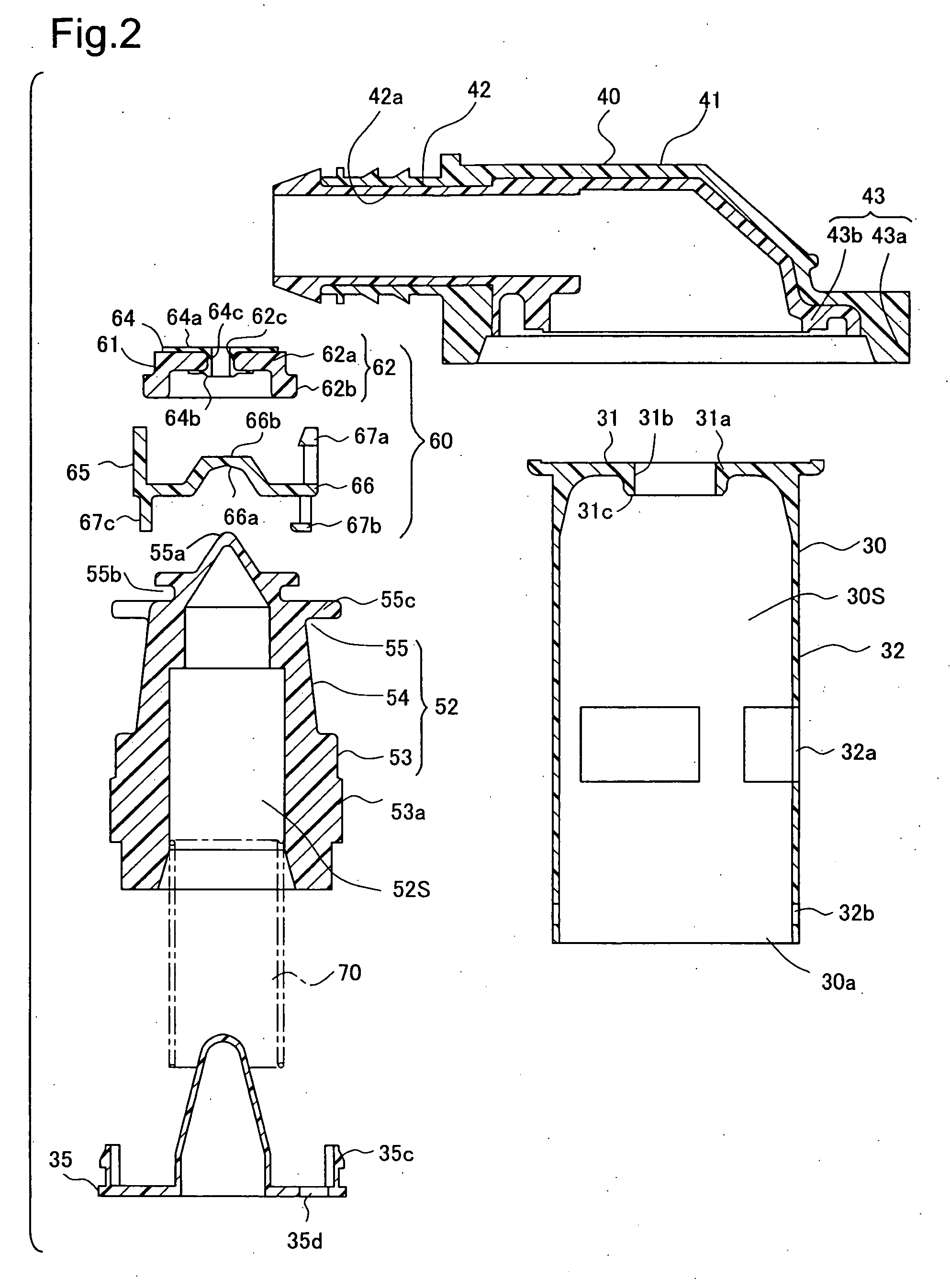
[0049] (2) Structure of Each Part of the Fuel Cut off Valve 10

[0050] The fuel cut off valve 10 comprises, as the primary structure thereof, a casing 20, a float...

second embodiment

B. Second Embodiment

[0072]FIG. 7 is a cross-sectional view showing the vicinity of the valve mechanism 60B of a fuel cut off valve according to the second embodiment. The second embodiment has, as its primary distinctive feature, a structure that improve the valve reopening characteristics of the valve mechanism 60B. The valve mechanism 60B comprises a first valve unit 61B, and a second valve unit 65B, above the float 52B. A seat member 64B is provided on a first valve main body 62B of the first valve unit 61B. The seat member 64B comprises an attachment part 64Ba that is pressed fitted into the first valve main body 62B, and a disk part 64Bb that is formed at the upper part of the outer periphery of the attachment part 64Ba, where these parts are integrally formed from a rubber material. The disk part 64Bb has a gap from the top surface of the first valve main body 62B, which, when seated against the seal part 31c, increases the sealing property through plastic deformation. A secon...

third embodiment

C. Third Embodiment

[0074]FIG. 8 is a cross-sectional view illustrating the fuel cut off valve according to a third embodiment. The third embodiment is a structure that is applied to a valve that prevents fuel from flowing out from a fuel tank when, for example, a vehicle is at an angle. A float mechanism 150 is housed within a casing 120, which has a connecting passage 131b within a fuel cut off valve 100. The float mechanism 150 comprises a valve mechanism 160, made from a first valve unit 161 and a second valve unit 165, and the top of a float 152. FIG. 9 is a prospective view of the assembly of the valve mechanism 160. In the first valve unit 161, a seat member 164 is integrated with a first valve main body 162, which has a connecting hole 164c. In the second valve unit 165, a second seat part 166b is fabricated in the center of the top surface of a second valve main body 166, and upper part retaining claws 167a, which hold the first valve unit 161, are fabricated on the upper pa...


PUM


Abstract

The fuel cut off valve comprises a casing, a float that rises and falls with increases and decreases in the buoyant force depending on the fuel liquid level within a valve chamber, and a valve mechanism that opens and closes a connecting passage through the rising or falling of the float, equipped on the upper part of the float. The valve mechanism comprises a supported part, and when the supported part is supported by a support part of the float, the center of gravity is provided below the support portion, so that the supported part is balanced on a single support portion. The fuel cut off valve can provide excellent seal performance when a vehicle is at an angle, and that can be miniaturized.

Description

[0001] This application claims the benefit of and priority from Japanese Applications No. 2004-338574 filed Nov. 24, 2004, No. 2005-22400 filed Jan. 31, 2005 and No. 2005220476 filed Sep. 29, 2005, the contents of which are incorporated herein by reference. BACKGROUND OF THE INVENTION [0002] 1. Field of the Invention [0003] The present invention relates to a fuel cutoff valve mounted on an upper wall of a fuel tank to open and close a connection passage, which connects the inside of the fuel tank with the outside. [0004] 2. Description of the Related Art [0005] A conventional fuel cutoff valve is described in JP-A-7-279789. The fuel cut off valve is mounted on the upper part of a fuel tank and comprises a casing, which has a connecting passage for connection to a canister, a float, which rises and falls with increasing or decreasing buoyant force due to a level of the liquid fuel in the valve chamber of the casing, and a upper valve unit disposed at the upper part of the float. The ...

Claims


Application Information

Patent Timeline
IPC IPC(8): F16K24/04
CPCB60K15/03519F16K24/044Y10T137/3099
Inventor KANEKO, KENICHIRONISHI, HIROSHIKITO, HIROAKISAKURAI, TOSHIYUKI
Owner TOYODA GOSEI CO LTD
Why Eureka
Try Eureka