Multiple pipe, method of manufacturing the multiple pipe and device for manufacturing multiple pipe

a manufacturing method and technology for multiple pipes, applied in the direction of engine components, mechanical equipment, machines/engines, etc., can solve the problems of difficulty in handling the pipe, poor appearance, and failure of each of the attempts to produce a suitable component, so as to reduce the amount of deformation irregularities, reduce the manufacturing cost, and improve the appearance. external

Inactive Publication Date: 2006-05-25
YAMAHA MOTOR CO LTD
View PDF2 Cites 6 Cited by
  • Summary
  • Abstract
  • Description
  • Claims
  • Application Information

AI Technical Summary

Problems solved by technology

Each of these attempts fails in its own regard to produce a suitable component.
Such a construction provides a poorly constructed appearance.
In addition, because the flanges protrude outward at both sides of the pipe, the flanges can cause difficulties during handling of the pipe.
The handling difficulties can adversely impact the assembly process as well as the serviceability of the pipe.
Further, a total of four pieces (i.e., two inner pipe components and two outer pipe components) need to be formed in advance and these components must be joined at both sides, which undesirably increases the manufacturing cost.
Similarly, in the second described arrangement, a total of four pieces (i.e., two inner pipe components and two outer pipe components) need to be formed and the outer pipe is welded, which results in an increased manufacturing cost.
Further, because of the need to weld the outer pipe, the external appearance of the final product is poor.
The handling properties of the pipe are deteriorated due to the welded portions, which results in adversely impacts assembling properties and serviceability.
With respect to the third described arrangement, when a glass wool, a catalyst or any other fibrous filler is disposed between any given pipes (e.g., between the inner and outer pipes for a double walled pipe), it is difficult to impregnate the fibrous filler with a liquid to freeze the inner part of the multiple pipe for bending.
In addition, it is difficult, if not impossible, to fully replace the air in the filler with a liquid.
Such a deflect results in a reduction in the sectional area of the pipe or large irregularities in the inside wall of the inner pipe due to folds or swellings.
Moreover, the outer pipe also will be formed with irregularities at the bend, which results in a poor external appearance.

Method used


Image

  • Multiple pipe, method of manufacturing the multiple pipe and device for manufacturing multiple pipe
  • Multiple pipe, method of manufacturing the multiple pipe and device for manufacturing multiple pipe
  • Multiple pipe, method of manufacturing the multiple pipe and device for manufacturing multiple pipe

Examples


Embodiment Construction

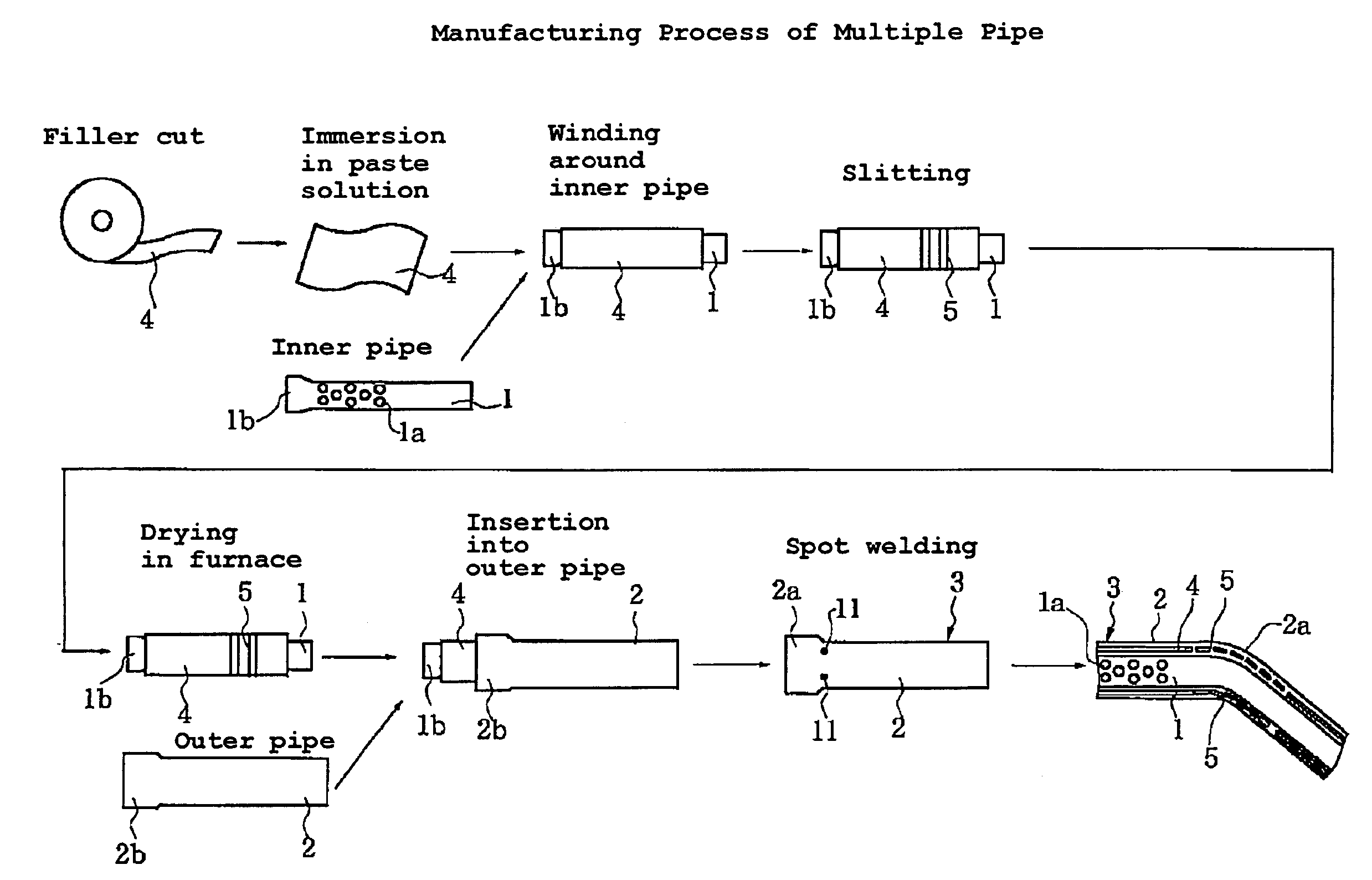
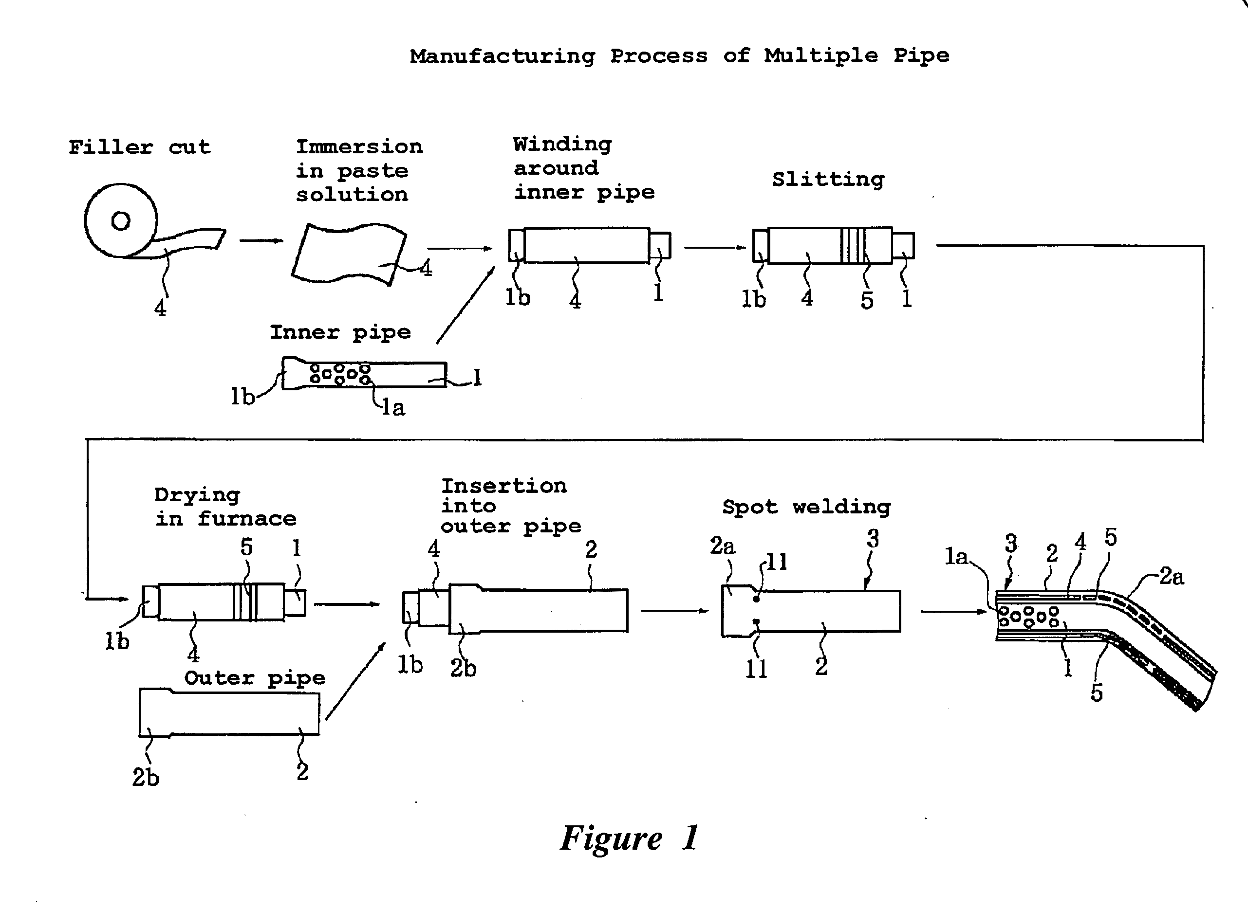
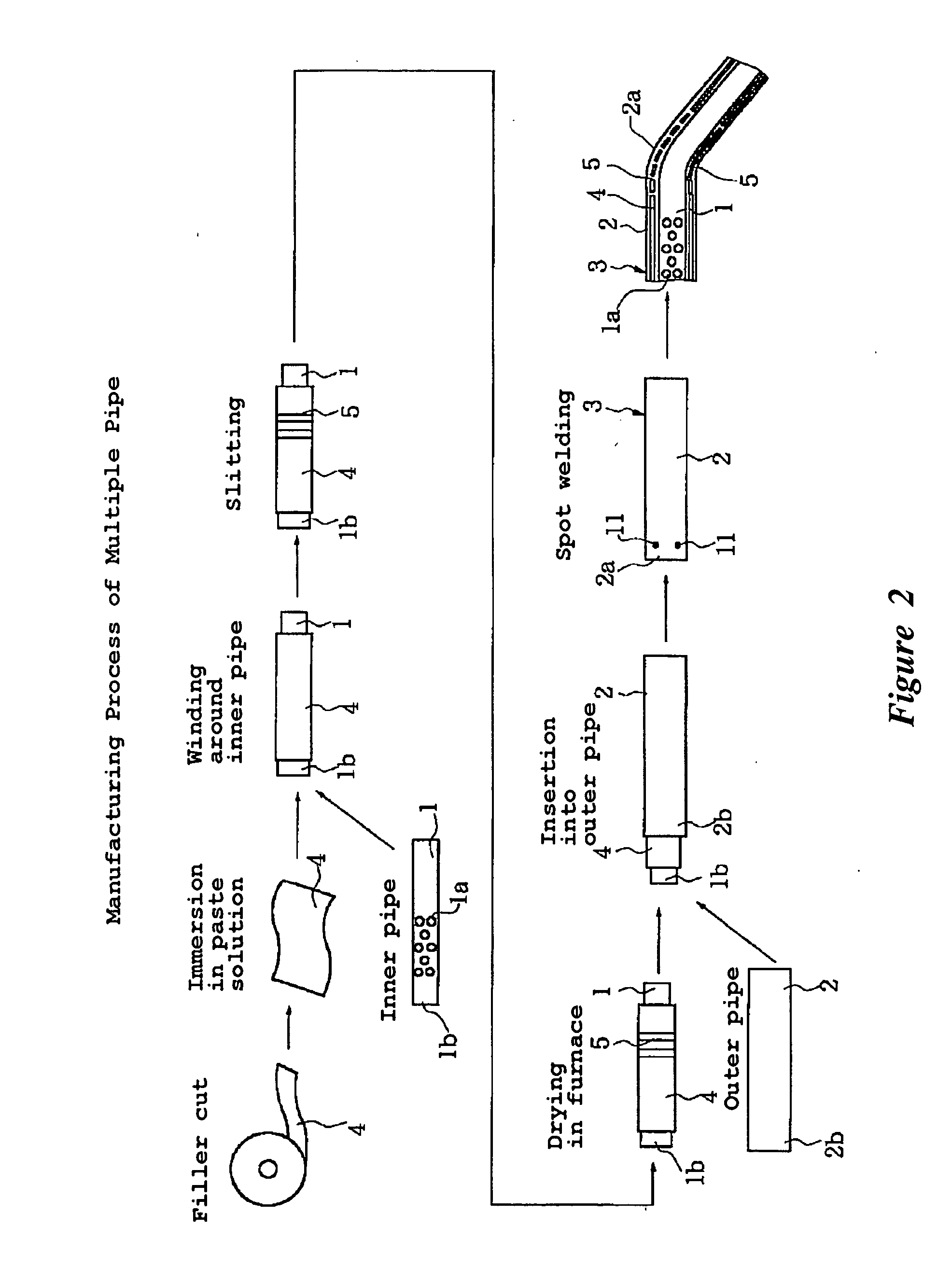
[0050] With reference now to the drawings, an embodiment of a multiple pipe component, a method of manufacturing the multiple pipe component and a device for manufacturing the multiple pipe component will be described below in detail. It should be understood that the embodiment herein described is with reference to but one embodiment of the invention and the present invention is not intended to be limited to this embodiment. According to the illustrated embodiment, a multiple pipe component that is made up of at least an inner pipe and an outer pipe with a bend can be obtained in which a fibrous filler is disposed at the pipe bending portion of the multiple pipe between the outer pipe and inner pipe. Furthermore, the illustrated embodiment facilitates the creation of such a component while reducing the cost of manufacture and assembly and increasing the quality of the component's external appearance.

[0051] As shown in FIGS. 1 and 2, a material pipe can be formed as a multiple pipe ...


PUM

PropertyMeasurementUnit
circumferential angleaaaaaaaaaa
angleaaaaaaaaaa

Abstract

The multiple pipe component is a pipe made up of at least an inner pipe and an outer pipe in which a fibrous filler is positioned between the outer pipe and the at least one inner pipe in a region that will be bent. The filler is formed with slits spaced at given pitches. Holes are provided in the inner pipe on at least one of the downstream side and the upstream side of the inner pipe in the bending region while holes are not disposed in the bending region.

Description

CROSS-REFERENCE TO RELATED APPLICATIONS [0001] This application is a continuation of International Patent Application No. PCT / JP04 / 07079, filed on May 24, 2004, which is based upon Japanese Patent Application No. 2003-146001, which was filed on May 23, 2003, each of which is hereby incorporated by reference in its entirety.BACKGROUND OF THE INVENTION [0002] 1. Field of the Invention [0003] The present invention generally relates to a multiple pipe component, such as an a double wall exhaust conduit that serves to conduct gases from the engine to the muffler or catalyst of a motorcycle, a snow mobile, a four-wheeled buggy or all terrain vehicle, or the like. The present invention also generally relates to bending a pipe that can be used in transporting liquids of solid bodies, such as powder and further substances each, composed in combination of any two or all of a gas, a liquid and a solid body. The present invention also relates to a method of manufacturing the multiple pipe compo...

Claims


Application Information

Patent Timeline
Patent Type & Authority Applications(United States)
IPC IPC(8): F16L9/14F01N13/08B21C37/06B21D9/00B21D9/15B21D9/16B21D53/84
CPCB21C37/06B21C37/157B21D9/15
Inventor NAKAJIMA, TOMOYUKIYOSHINO, TAMIOTASHIRO, YOJI
Owner YAMAHA MOTOR CO LTD
Why Eureka
Try Eureka