Roller rotary offset printing press having at least one coating unit with a chamber blade and an anilox roller

a technology of offset printing press and roller, which is applied in the direction of rotary presses, printing, office printing, etc., can solve the problems of relatively high equipment requirements and the use of varnishes, and achieve the effects of preventing the web speed decrease low moisture content of the print substrate, and high absorbency

Inactive Publication Date: 2012-05-17
KOENIG & BAUER AG
View PDF1 Cites 6 Cited by
  • Summary
  • Abstract
  • Description
  • Claims
  • Application Information

AI Technical Summary

Benefits of technology

[0013]The benefits to be achieved by the invention consist particularly in that the printed products treated by the coating unit have several of the advantages over uncoated printed products, such as improved gloss and contrast and greatly diminished smearing behavior, and a high-quality look of the paper, which can typically be achieved with coating devices, although the coating unit is relatively simple in structure, and does not require a dryer downstream. Therefore, costs can be reduced by using more cost-efficient paper.
[0026]A further advantage consists in that the coating unit can be embodied in various configurations, for example, with a small number of rollers, in order to decrease cost, or with a large number of rollers, including flexo printing rollers or rollers for double-sided coating, for example, in order to further increase coating quality.

Problems solved by technology

Therefore, the use of such varnishes is relatively costly in terms of the equipment required.

Method used


Image

  • Roller rotary offset printing press having at least one coating unit with a chamber blade and an anilox roller
  • Roller rotary offset printing press having at least one coating unit with a chamber blade and an anilox roller
  • Roller rotary offset printing press having at least one coating unit with a chamber blade and an anilox roller

Examples


embodiment example 1

“Direct, with Wrap”

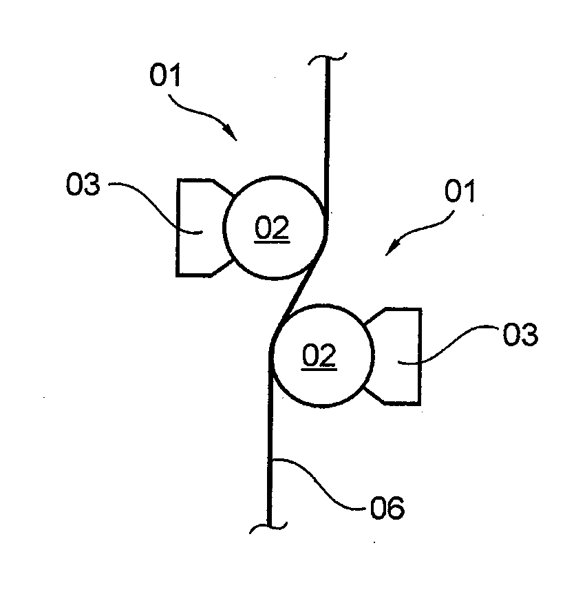
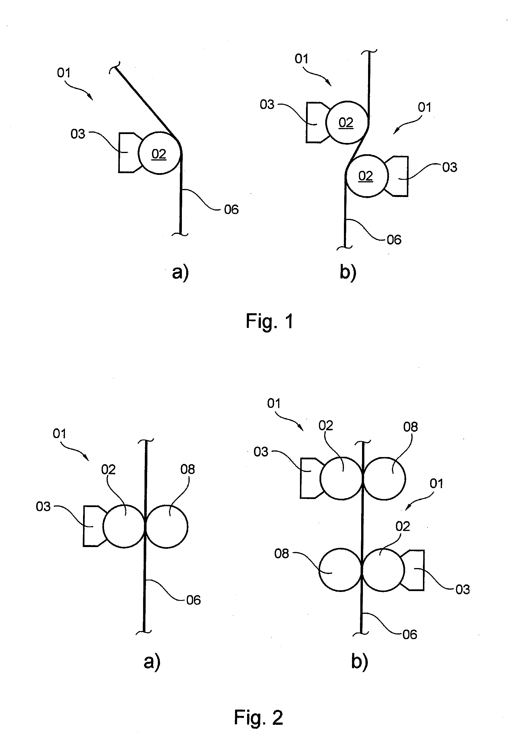
[0050]This embodiment example is also illustrated in FIG. 1a). The web of print substrate 06 is in direct contact with the anilox roller 02 during print operation. The varnish is therefore transferred from the depressions in the outer surface of the anilox roller 02 directly onto the print substrate 06. The varnish spots transferred from the individual depressions continue to spread somewhat after they are transferred, and they become joined with one another, so that at the desired locations on the print substrate 06, a continuous varnish surface is produced. For this purpose, a relatively fine-screened anilox roller 02 is used, which means that in the case of a linear structure, the density of the lines is preferably between 90 and 130 lines per cm. The print substrate 06 is pressed by wrapping against the anilox roller 02, i.e., the print substrate 06 is in contact with the anilox roller 02 not merely along a line that extends parallel to a rotational axis of th...

embodiment example 2

“Direct, with Counterpressure”

[0052]This embodiment example is also illustrated in FIG. 2a). As in embodiment example 1, the print substrate 06 is coated with varnish directly by the anilox roller 02. The anilox roller 02 is embodied as in embodiment example 1, and the varnish is transferred in exactly the same way as in embodiment example 1, including the spreading of the transferred varnish spots at the desired points on the print substrate 06 to form a continuous coating surface. An impression cylinder 08 presses the print substrate 06 against the anilox roller 02 in order to achieve better contact between anilox roller 02 and print substrate 06, and thereby improve the transfer of the varnish from the depressions in the anilox roller 02 onto the print substrate 06. The print substrate 06 can wrap around the anilox roller 02 and / or the impression cylinder 08, or can be guided in a straight line between the anilox roller 02 and the impression cylinder 08, i.e., a zone of contact b...

embodiment example 3

“With Forme Roller, with Wrap”

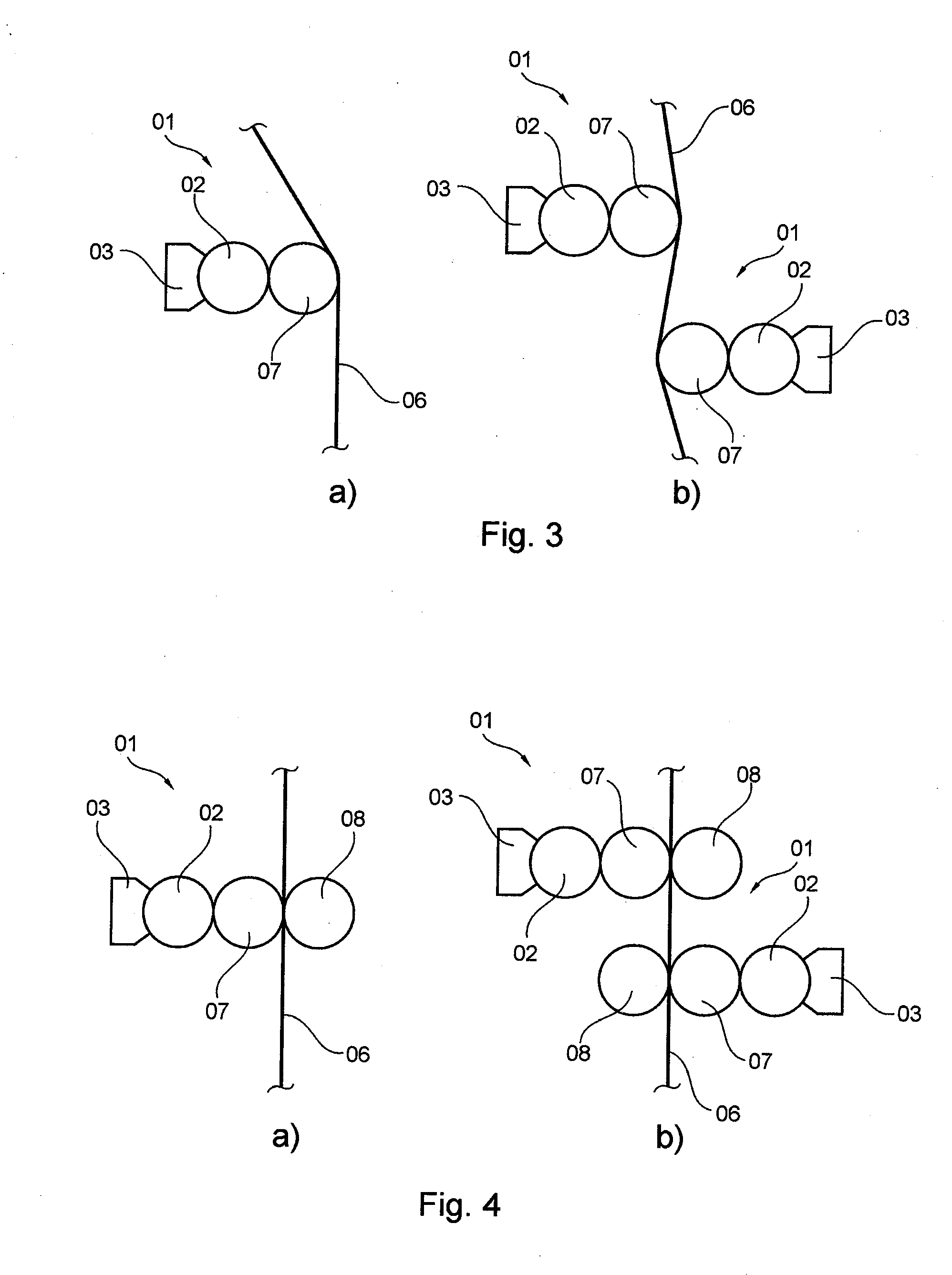
[0054]This embodiment example is also illustrated in FIG. 3a). The anilox roller 02 is in contact with both the chamber doctor blade 03 and a forme roller 07. The forme roller 07 is in turn in rolling contact with the print substrate 06. Because the print substrate 06 is not in direct contact with the anilox roller 02, if the depressions in the outer surface of the anilox roller 02 have a linear structure, the density of the lines preferably ranges from 40 to 80 lines per cm. The print substrate 06 wraps around the forme roller 07, and therefore, the contact between forme roller 07 and print substrate 06 is embodied not as a line but as a surface, and contact pressure between print substrate 06 and forme roller 07 is produced. Varnish is transferred out of the interior of the chamber doctor blade 03 via the anilox roller 02 to the forme roller 07, and from there to the print substrate 06. The portion of an outer surface of the forme roller 07 that is in...


PUM


Abstract

A roller rotary offset printing press has at least one coating unit and at least one printing unit. The coating unit comprises at least one coating unit and at least one printing unit. The coating unit comprises at least one chamber blade having a water-based coating and at least one anilox roller. The coating unit is arranged along a transport path of a print stock downstream of the at least one printing unit of the roller rotary offset printing press. At least one pair of two rollers is arranged that together form a coating gap. At least one roller of the at least one pair is in contact with the at least one anilox roller. The conveyed volume, at least on one part of the shell surface of the at least one anilox roller, is filled by an amount of coating, the mass of which, based on this part of the shell surface of the at least one anilox roller, minus a water portion, equals, on average, a maximum of 4 g / m2. A blanket having several layers can be placed or is placed on at least one roller of the coating unit.

Description

CROSS-REFERENCE TO RELATED APPLICATIONS[0001]This application is the U.S. National Phase, under 35 USC 371, of PCT / EP2010 / 054077, filed Mar. 29, 2010; published as WO 2010 / 127913 A1 on Nov. 11, 2010 and claiming priority to DE 10 2009 002 228.7, filed Apr. 6, 2009, the disclosures of which are expressly incorporated herein by reference.FIELD OF THE INVENTION[0002]The invention relates to methods for using a web-fed rotary printing press, and to a web-fed rotary offset printing press having at least one coating unit and at least one printing couple.[0003]The printing press has at least one coating unit and at least one printing couple. The coating unit includes at least one chamber doctor blade containing a water-based varnish and at least one anilox roller which has a plurality of depressions in its outer surface that together form a clip volume. The coating unit is disposed downstream of the at least one printing couple of the web-fed rotary printing press along a transport route o...

Claims


Application Information

Patent Timeline
Patent Type & Authority Applications(United States)
IPC IPC(8): B41F3/34
CPCB41F23/08B41F31/027
Inventor MASUCH, BERND KURTREDER, WOLFGANG OTTO
Owner KOENIG & BAUER AG
Why Eureka
Try Eureka