Enclosures for fluidic oscillators

a technology of fluidic oscillator and enclosure, which is applied in the direction of circuit elements, thin material processing, vehicle cleaning, etc., can solve the problems that the nature of the enclosure or enclosure that surrounds the fluidic oscillator has not changed much, and achieves the effect of improving the actual spray performance of the spray device, large surface area, and large diameter

Active Publication Date: 2006-05-25
DLHBOWLES INC
View PDF28 Cites 45 Cited by
  • Summary
  • Abstract
  • Description
  • Claims
  • Application Information

AI Technical Summary

Benefits of technology

[0018] There has been summarized above, rather broadly, the prior art that is related to the present invention in order that the context of the present invention may be better understood and appreciated. In this regard, it is instructive to also consider the objects and advantages of the present invention.
[0019] It is an object of the present invention to provide an assortment of individual housings or enclosures for fluidic oscillators that can be helpful in improving upon the actual spray performance of the spray devices or nozzle assemblies that utilize fluidic oscillators.
[0020] It is an object of the present invention to provide fluidic spray assemblies (i.e., fluidic oscillators with novel enclosures) that can provide specific types of desired sprays that have heretofore not been achievable with conventional fluidic technology. For example, to uniformly cover a relatively large surface area (e.g., a 400 cm area at a distance of 30 cm from the spray head's exit) with liquid droplets that have large diameters (e.g., >2 mm), high velocities (e.g., >or ˜4 m / sec) and possibly pulsating frequencies that are in the range of perception by the human body (e.g., <or ˜30-60 hertz).
[0021] It is an object of the present invention to provide improved and more versatile enclosures and fluidic spray assemblies that are ideally designed for shower head and body spray applications.
[0022] It is an object of the present invention to provide enclosures and fluidic spray assemblies that operate at low flow rates in shower head and body spray applications so as to yield significant water savings.
[0023] It is an object of the present invention to provide improved enclosures and fluidic spray assemblies that are ideally designed for an assortment of commercial cleaning applications.

Problems solved by technology

Despite much prior art relating to the development of fluidic circuits, the nature of the housings or enclosures that surround fluidic oscillators have not changed much over the years.

Method used


Image

  • Enclosures for fluidic oscillators
  • Enclosures for fluidic oscillators
  • Enclosures for fluidic oscillators

Examples


Embodiment Construction

[0055] Before explaining at least one embodiment of the present invention in detail, it is to be understood that the invention is not limited in its application to the details of construction and to the arrangements of the components set forth in the following description or illustrated in the drawings. The invention is capable of other embodiments and of being practiced and carried out in various ways. Also, it is to be understood that the phraseology and terminology employed herein are for the purpose of description and should not be regarded as limiting.

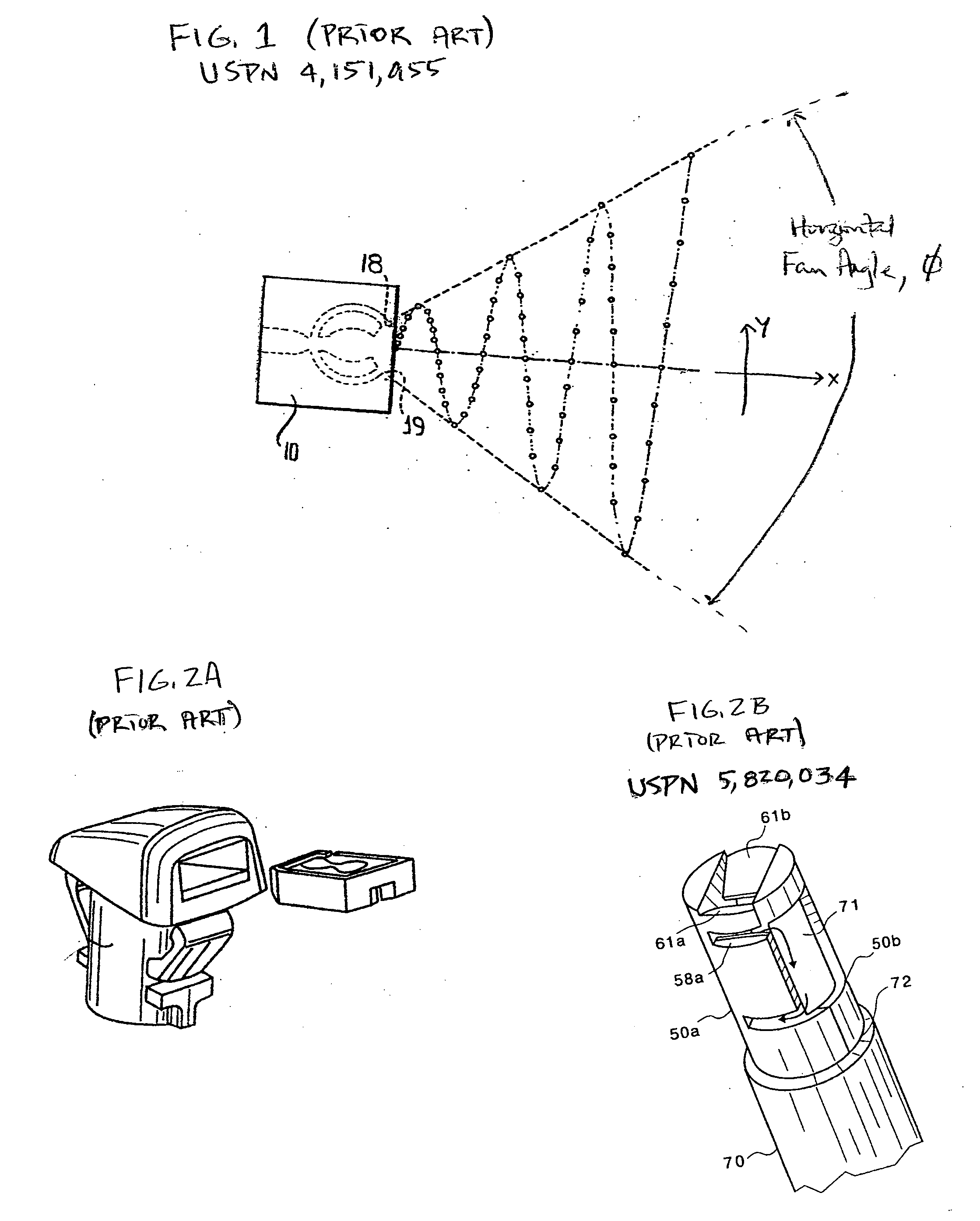
[0056] A common problem encountered in developing and producing fluidic oscillators or inserts for use in automotive windshield applications is designing a fluidic circuit which can give the desired spray characteristics (e.g., at flow rates of 400 ml / minute and operating pressures of 9 psig, uniform coverage with spray droplets of a target area located approximately 25 cm in front of the sprayer and having a target area width of...


PUM


Abstract

For those spray applications that use a fluidic oscillator of the type that generates a spray by having a pressurized liquid flow through the oscillator and exhaust into a surrounding environment, and where such an oscillator has a boundary surface which has fabricated into it a channel in the form of what is referred to herein as fluidic circuit, an improved enclosure for this oscillator includes: a body having an interior and an exterior surface, wherein a portion of this interior surface is configured to attach to the oscillator boundary surface so as to form with the oscillator's channel an enclosed pathway through which the to-be-sprayed liquid may flow, and wherein a segment of this interior surface is configured so as to yield specified properties of the resulting spray.

Description

CROSS-REFERENCE TO RELATED APPLICATION [0001] This application is a continuation-in-part of applicants' co-pending application U.S. Ser. No. 10 / 673,727, Attorney Docket No. BWLS13, filed Sep. 29, 2003, and titled “Fluid Spray Apparatus.”BACKGROUND OF THE INVENTION [0002] 1. Field of the Invention [0003] This invention relates to fluid handling processes and apparatus. More particularly, this invention relates to new methods and apparatus for enclosing fluidic oscillators or inserts so as to improve their performance. [0004] 2. Description of the Related Art [0005] Fluidic inserts or oscillators are well known for their ability to provide a wide range of distinctive liquid sprays. The distinctiveness of these sprays is due to the fact that they are characterized by being oscillatory in nature, as compared to the relatively steady state flows that are emitted from standard spray nozzles. [0006]FIG. 1 from U.S. Pat. No. 4,052,002 (Stouffer & Bray) demonstrates the oscillatory nature of...

Claims


Application Information

Patent Timeline
Patent Type & Authority Applications(United States)
IPC IPC(8): B05B1/08B05B3/04
CPCB05B1/08B05B1/14B05B1/18B60S1/52Y10T137/2224
Inventor RUSSELL, GREGORYBERNING, KEITHHESTER, RUSSELL D.
Owner DLHBOWLES INC
Why Eureka
Try Eureka