Robot controller and robot system

Active Publication Date: 2006-05-25
YASKAWA DENKI KK
View PDF35 Cites 44 Cited by
  • Summary
  • Abstract
  • Description
  • Claims
  • Application Information

AI Technical Summary

Benefits of technology

[0098] As understood from the above explanation, in accordance with the robot control apparatus according to this invention, while a teacher performs the teaching in access to a robot or work holding device or within the operation range of the robot, even if the operation of the robot not intended by the teacher occurs owing to the erroneous manipulation of the pendant, since the robot is controlled at a low speed, the time enough for the teacher to take an evading action can be assured, thereby providing the effect of enhancing safety of the teacher.
[0099] Further, only if the wrist of the robot or working tool comes near the teacher, the maximum operating speed of the robot is reduced so that safety of the teacher can be enhanced. In addition, since the maximum operating speed of the robot is increased at a position remote from the working position by the robot, i.e. the teacher, attenuation of the teaching efficiency can be minimized.
[0100] Further, in accordance with this invention, in a situation where a plurality of robots are ar

Problems solved by technology

However, where the teaching area difficult to confirm visually is taught or the point of teaching is finely adjusted, the operator comes near the robot.
In such a case, between the first operator teaching the first robot and the second operator teaching the second robot, because of the operation based on the subjective impression or carelessness by the second operator, the second robot may give serious injury to the first operator through the operation directed to the first operator who stands within the operation region of the second robot or interference and collision with him.
Also in a production system in which a plurality of robots are controlled by a single robot control apparatus, where an operator performs teaching in an operating range of the plurality of robots, because of the operation based on the subjective impression or carelessness by the operator, as in the case, there is a danger that the robot which is not the object for teaching gives serious injury to the operator through the operation directed to the operator and or interference and collision with him.
In a conventional robot control apparatus, these inconveniences was dealt with by interrupting the power source of driving the other robot than the operating object, thereby braking each of axial motors.
In this case, if the pendant is erroneously manipulated, the robot makes the operation not intended by the teacher so that the teacher is surprised.
However,

Method used


Image

  • Robot controller and robot system
  • Robot controller and robot system
  • Robot controller and robot system

Examples


embodiment 1

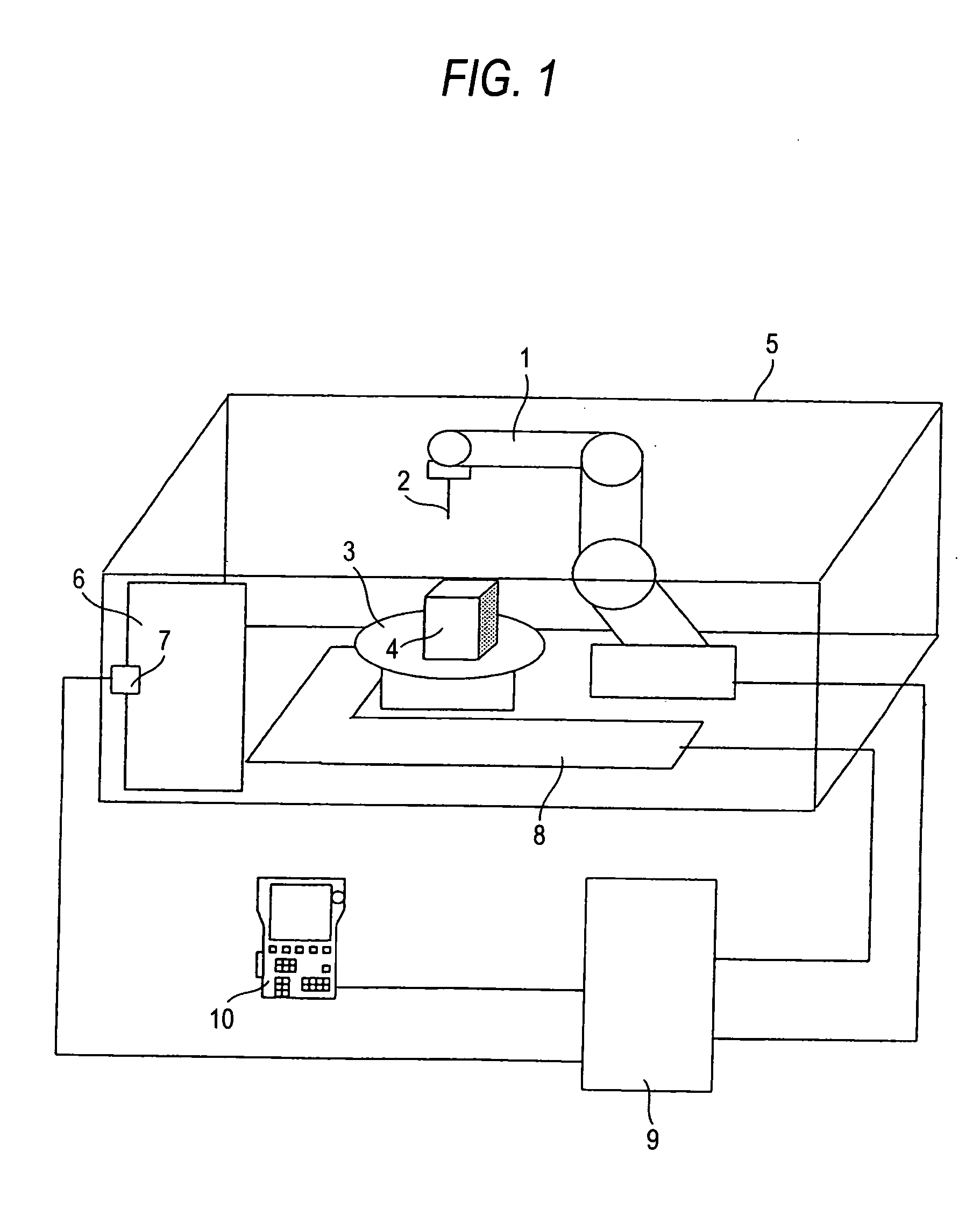
[0115]FIG. 1 is a view of the configuration of a robot system illustrating a first embodiment of this invention.

[0116] In FIG. 1, reference numeral 1 denotes a robot connected to a robot control apparatus. A working tool 2 for working is attached to the tip of a wrist of a robot 1. The robot control device is connected to a pendant 10 employed to conduct the editing such as registering of a working program, or changing of a registered working program by operating the robot 1, performing registering of a position thereof or registering of a work. The robot control apparatus includes a safety shelf surrounding the operating range of the robot 1, a safety shelf door 6 to a gateway to the safety shelf, and a safety shelf door opening / closing detecting device 7 for detecting the opened / closed status of the safety shelf door 6. An output signal from the safety shelf door opening / closing device 7 is connected to the robot control device 9.

[0117] A detecting device 8 is installed in the v...

embodiment 2

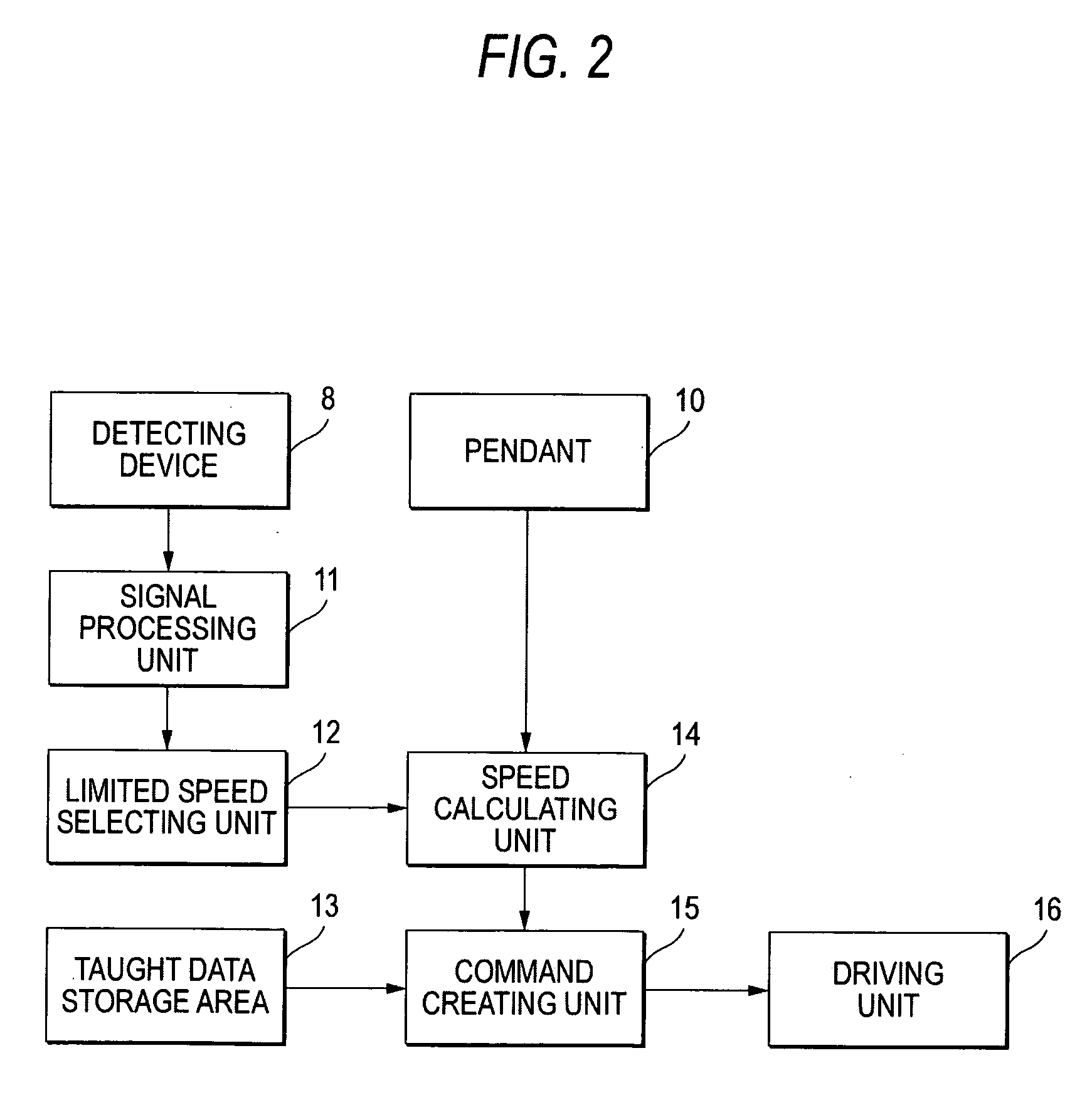
[0127]FIG. 4 is a block diagram of speed control according to the second embodiment of this invention. A driving unit 16 is provided with a position detector capable of detecting a position. On the basis of the signal from this position detector, a robot position calculating unit 17 calculates the present position of the robot. The limited speed selecting unit 12 selects the maximum speed on the basis of the outputs from the signal processing unit 11 and robot position calculating unit 17. The manner of selection will be explained below on the basis of a configuration view.

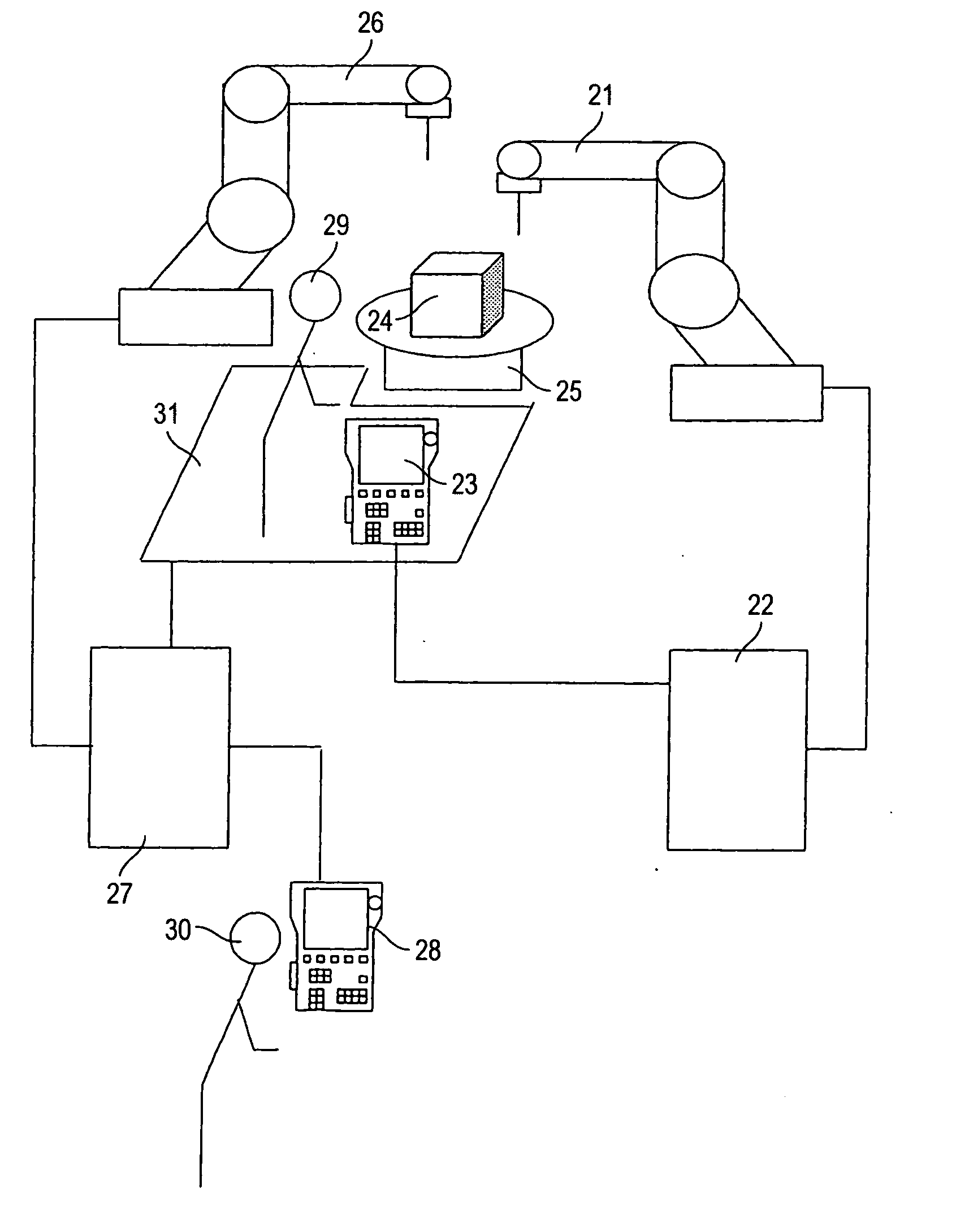
[0128]FIG. 3 is a view showing the configuration of a robot system showing the second embodiment of this invention.

[0129] In FIG. 3, reference numeral 1 denotes a robot connected to a robot control device 9. A work 4a and a work 4b for which working is to be carried out are arranged on the left and right side of the robot 1, respectively. Reference numerals 8a and 8b denote a plurality of detecting devices. When...

embodiment 3

[0137] Now referring to FIG. 5, an explanation will be given of the third embodiment of this invention. The third embodiment intends to control the operating speed of the robot 1 on the basis of only the present position of the robot computed by the robot position computing unit 17.

[0138] The speed limited region in a robot operating range and the maximum operating speed in the speed limited region are stored in a storage area not shown.

[0139] The speed limited region can be defined in such a manner that the robot 1 is operated to register two end points, or the coordinate values of robot coordinates are registered by direct inputting from the pendant. These manners permit a rectangular parallelepiped to be defined on the robot coordinates.

[0140] In the robot control device 9, the position of the end effecter of the robot 1 is periodically computed by the robot position computing unit 17 using the information from the position detector of each servo axis. If this position is with...


PUM


Abstract

A robot control apparatus with great safety is provided by detecting access of a teacher to a robot and automatically reducing the operating speed of the robot when the teacher accesses the robot. The robot control device equipped with a pendant (10) to be manipulated by a teacher, for controlling the operation of a robot on the basis of an operation command from the pendant (10), includes a detecting device (8) for detecting the position of the teacher; a signal processing unit (11) for receiving a signal from the detecting device to produce the position information of the teacher; and a limited speed selecting unit (12) for selecting the operating speed of the robot on the basis of the position information. The robot is controlled at the maximum speed set at the operating speed selected by the limited speed selecting unit (12) on the basis of the operation command from the pendant (10).

Description

TECHNICAL FIELD [0001] This invention relates to a robot in a teaching playback system, and more particularly to a robot control apparatus for assuring safety of a worker or operator during working in access to a robot by limiting a pendant operation of a teacher in access to the robot during teaching, or the operation of the robot not watched carefully by the worker or operator. BACKGROUND ART [0002] Now referring to the drawing, an explanation will be given of a conventional robot control apparatus. FIG. 12 is a view showing the configuration of the conventional robot control apparatus. [0003] In FIG. 12, reference numeral 101 denotes a robot connected to a robot control apparatus 105. A working tool 102 for working is attached to the tip of a wrist of the robot 101. The robot control device 105 is connected to a pendant 106 employed to conduct the editing such as registering of a working program, or changing of a registered working program by operating the robot 101, performing r...

Claims


Application Information

Patent Timeline
IPC IPC(8): B25J15/02B25J9/16B25J19/06B25J21/00G05B19/4061G05B19/416
CPCB25J9/1676B25J19/06B25J21/00G05B19/4061G05B19/416G05B2219/49138G05B2219/49152G05B2219/49158B25J9/1674
Inventor TANAKA, MICHIHARUKARIYAZAKI, HIROKAZUYAMAMOTO, MINORU
Owner YASKAWA DENKI KK
Why Eureka
Try Eureka