Digital signal coding apparatus, digital signal decoding apparatus, digital signal arithmetic coding method and digital signal arithmetic decoding method

a digital signal and coding apparatus technology, applied in the field of digital signal coding apparatus, digital signal arithmetic coding method, digital signal coding method, can solve the problems of inability to operate with infinite decimal precision, affecting the coding efficiency of arithmetic coding, and not being able to guarantee optimal performance, etc., to achieve the effect of improving the coding efficiency and high degree of error resilien

Inactive Publication Date: 2006-05-25
XYLENE HLDG SA
View PDF18 Cites 46 Cited by
  • Summary
  • Abstract
  • Description
  • Claims
  • Application Information

AI Technical Summary

Benefits of technology

[0019] With this, it is possible to continue coding across bounds of transmission units by inheriting, instead of resetting, the earlier arithmetic coding status or the symbol probability learning status. Thus, a high degree of error resilience and an improved coding efficiency of arithmetic coding result.

Problems solved by technology

Optimum performance is not, however, guaranteed when a signal such as a video signal exhibits localized variation so that the probability of appearance of information symbols varies.
In actual implementation, it is impossible to operate with infinite decimal precision.
Moreover, multiplication and division are necessary for coding and decoding so that heavy computational load is imposed.
As a result, the coding efficiency may suffer prior to and subsequent to the suspension.
Another problem to be addressed is that, when an arithmetic coding process is not reset while coding a video frame and the frame has to be divided into small units such as packet data for transmission, decoding of a packet cannot take place without the immediately preceding packet data so that significant adverse effects on video quality result when a transmission error or a packet loss due to a delay occurs.

Method used


Image

  • Digital signal coding apparatus, digital signal decoding apparatus, digital signal arithmetic coding method and digital signal arithmetic decoding method
  • Digital signal coding apparatus, digital signal decoding apparatus, digital signal arithmetic coding method and digital signal arithmetic decoding method
  • Digital signal coding apparatus, digital signal decoding apparatus, digital signal arithmetic coding method and digital signal arithmetic decoding method

Examples


first embodiment

[0044] A first embodiment of the present invention is presented using an example, disclosed in D. Marpe et al. “Video Compression Using Context-Based Adaptive Arithmetic Coding”, International Conference on Image Processing 2001, in which arithmetic coding is applied to a video coding scheme where a square area of 16×16 pixels (hereinafter, referred to as a macroblock) produced by uniformly dividing a video frame is a coding unit.

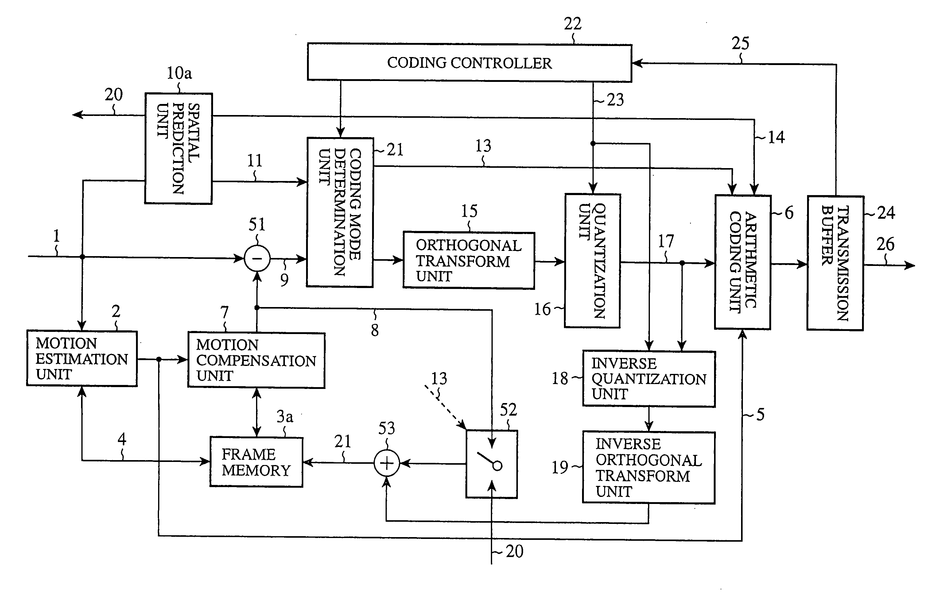
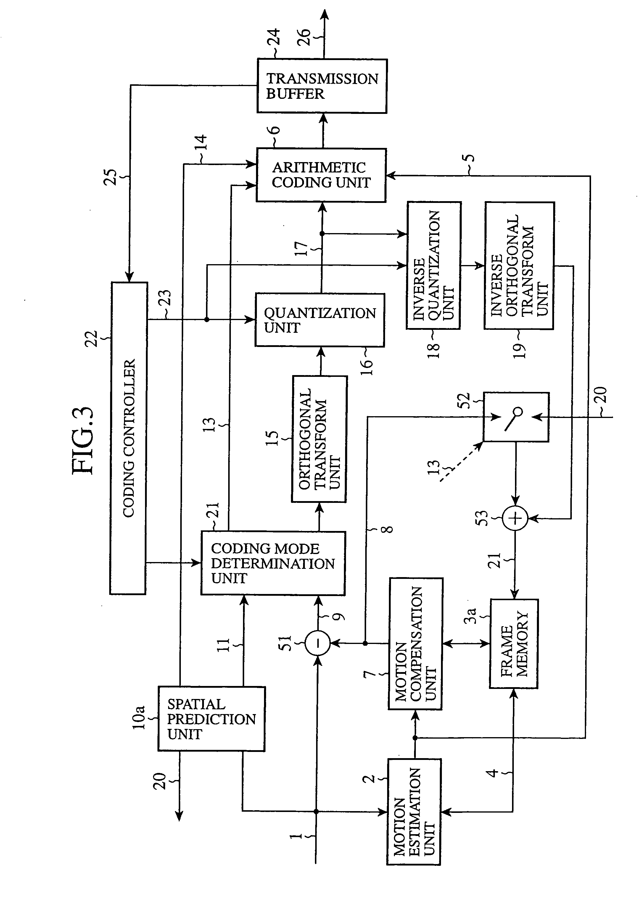
[0045]FIG. 3 shows a construction of a video coding apparatus (digital signal coding apparatus) according to the first embodiment of the present invention. Referring to FIG. 3, a motion estimation unit 2 extracts a motion vector 5 for each of the macroblocks of an input video signal 1, using a reference image 4 stored in a frame memory 3a. A motion compensation unit 7 constructs a temporal predicted image 8 based on the motion vector 5 extracted by the motion estimation unit 2. A subtractor 51 determines a difference between the input video signal 1 and th...

second embodiment

[0141] An alternative configuration of the arithmetic coding unit 6 and the arithmetic decoding unit 27 according to the second embodiment will now be described. In the second embodiment, not only the register value indicating the status of a codeword from the arithmetic coding process but also the status of learning of a variation of probability estimate in a context model is multiplexed into the slice header. The status of learning occurs in the probability generation unit 30 as the unit updates the probability of occurrence of each bin.

[0142] For example, referring to FIG. 8 in the first embodiment, in order to improve the arithmetic coding efficiency for block C, information on the motion vector for block B above block C is exploited to determine a variation of probability estimate. Accordingly, if block C and block B are located in difference slices, the information on block B should be prevented from being used to determine the probability of occurrence.

[0143] This means tha...

third embodiment

[0166] A disclosure will now be given of the third embodiment in which transmission units are constructed according to a data partitioning format in which coding data are grouped according to a data type.

[0167] The example explained below is taken from Working Draft Number 2, Revision 3, JVT-B118r3 for a video coding scheme discussed in Joint Video Team (JVT) of ISO / IEC MPEG and ITU-T VCEG. The draft discloses as many data items of a specific type as there are macroblocks in a slice structure as shown in FIG. 9, are grouped. The resultant data unit is transmitted in the form of slice data. The slice data (data unit) constructed by grouping is of one of data types 0-7 such as those shown below, for example.

0 TYPE_HEADER picture (frame) or slice header

1 TYPE_MBHEADER macroblock header information (coding mode information)

2 TYPE_MVD motion vector

3 TYPE_CBP CBP (non-zero orthogonal transform coefficient pattern in macroblock)

4 TYPE—2×2DC orthogonal transform coefficient data ...


PUM


Abstract

In a bit stream syntax containing compressed video slice data for compressed video data of a slice structure, a slice header for compressed video slice data has attached thereto a slice start code, a register reset flag indicating whether a register value, which designates a status of a codeword occurring in an arithmetic coding process, should be reset in the next transmission unit, an initial register value which indicates a register value to be used to start arithmetic coding / decoding to build / decompose the next transmission unit, only when the register reset flag indicates that the register should not be reset.

Description

CROSS REFERENCE TO RELATED APPLICATIONS [0001] This application is a Divisional of co-pending application Ser. No. 10 / 480,046, filed on Sep. 9, 1003, for which priority is claimed under 35 U.S.C. § 120. Application Ser. No. 10 / 480,046 is the national phase of PCT International Application No. PCT / JP03 / 04578 filed on Apr. 10, 2003 under 35 U.S.C. § 371, which international application claims priority under 35 U.S.C. § 119(a)-(d) on Japanese Application No. 2002-124114, filed on Apr. 25, 2002. The entire contents of each of these applications are hereby incorporated by reference.TECHNICAL FIELD [0002] The present invention relates to a digital signal coding apparatus, a digital signal decoding apparatus, a digital signal arithmetic coding method and a digital signal arithmetic decoding method used for video compression coding and compressed video data transmission. BACKGROUND ART [0003] In International standards for video coding such as MPEG and ITU-T H.26x, Huffman coding has been u...

Claims


Application Information

Patent Timeline
Patent Type & Authority Applications(United States)
IPC IPC(8): H03M7/00G06T9/00H03M7/40H04N7/24H04N7/52H04N19/00H04N19/105H04N19/13H04N19/174H04N19/46H04N19/51H04N19/593H04N19/625H04N19/70H04N19/91
CPCH03M7/40H04N19/174H04N7/52H04N21/2381H04N21/4363H04N21/4381H04N19/105H04N19/176H04N19/70H04N19/46H04N19/13H04N19/61H04N19/107H04N19/124H04N19/137H04N19/152H03M7/4006
Inventor SEKIGUCHI, SHUNICHIYAMADA, YOSHIHISAASAI, KOHTARO
Owner XYLENE HLDG SA
Why Eureka
Try Eureka